
How to Use PID Controller: Examples, Pinouts, and Specs
 Design with PID Controller in Cirkit Designer
Introduction
The RS Pro 7983472 PID Controller is a versatile and reliable control loop feedback mechanism designed for industrial automation and process control applications. It calculates the error between a desired setpoint and a measured process variable, then applies corrections using proportional, integral, and derivative terms to minimize the error. This ensures precise and stable control of processes such as temperature, pressure, flow, and more.
Explore Projects Built with PID Controller
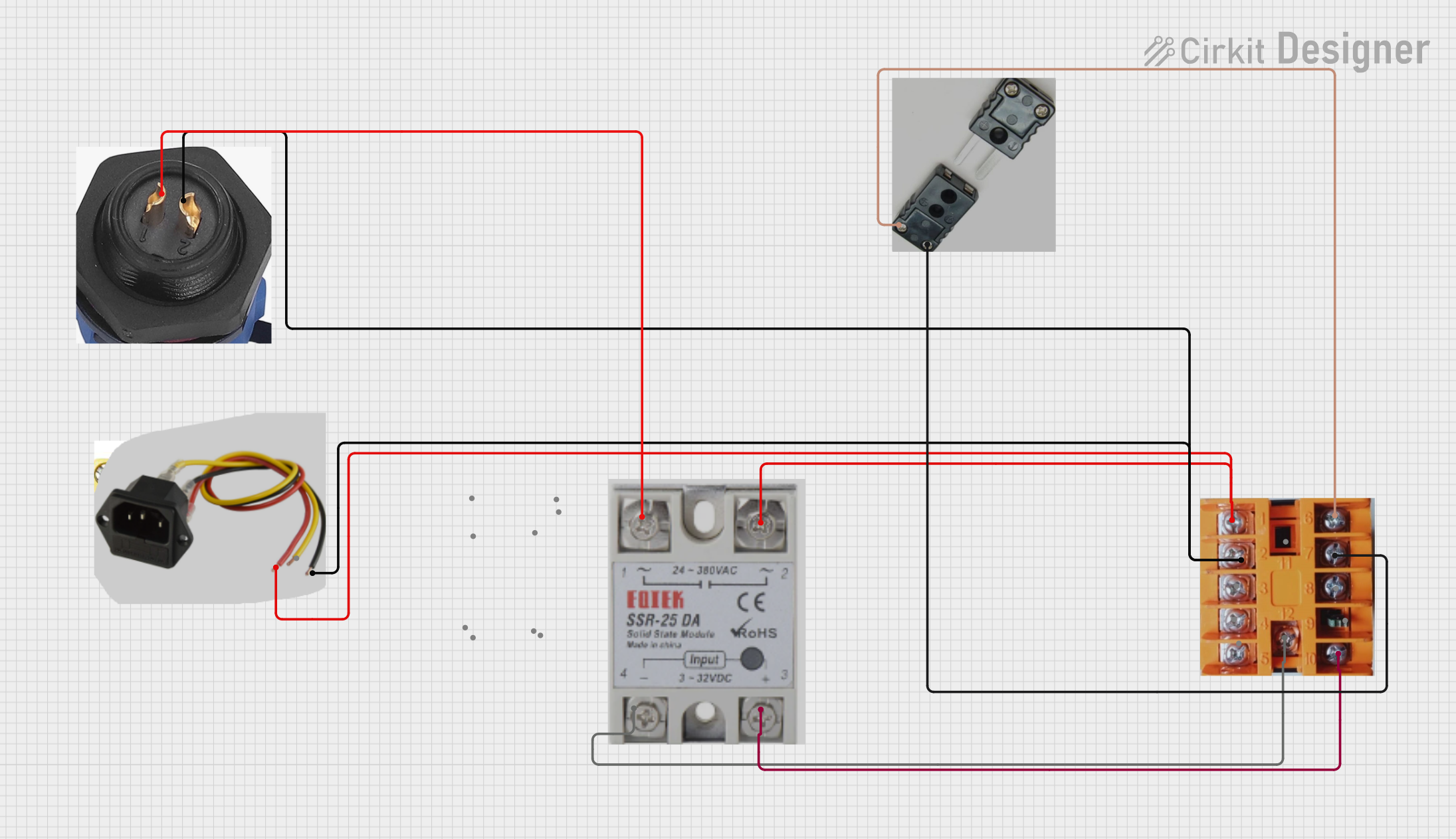 Open Project in Cirkit Designer
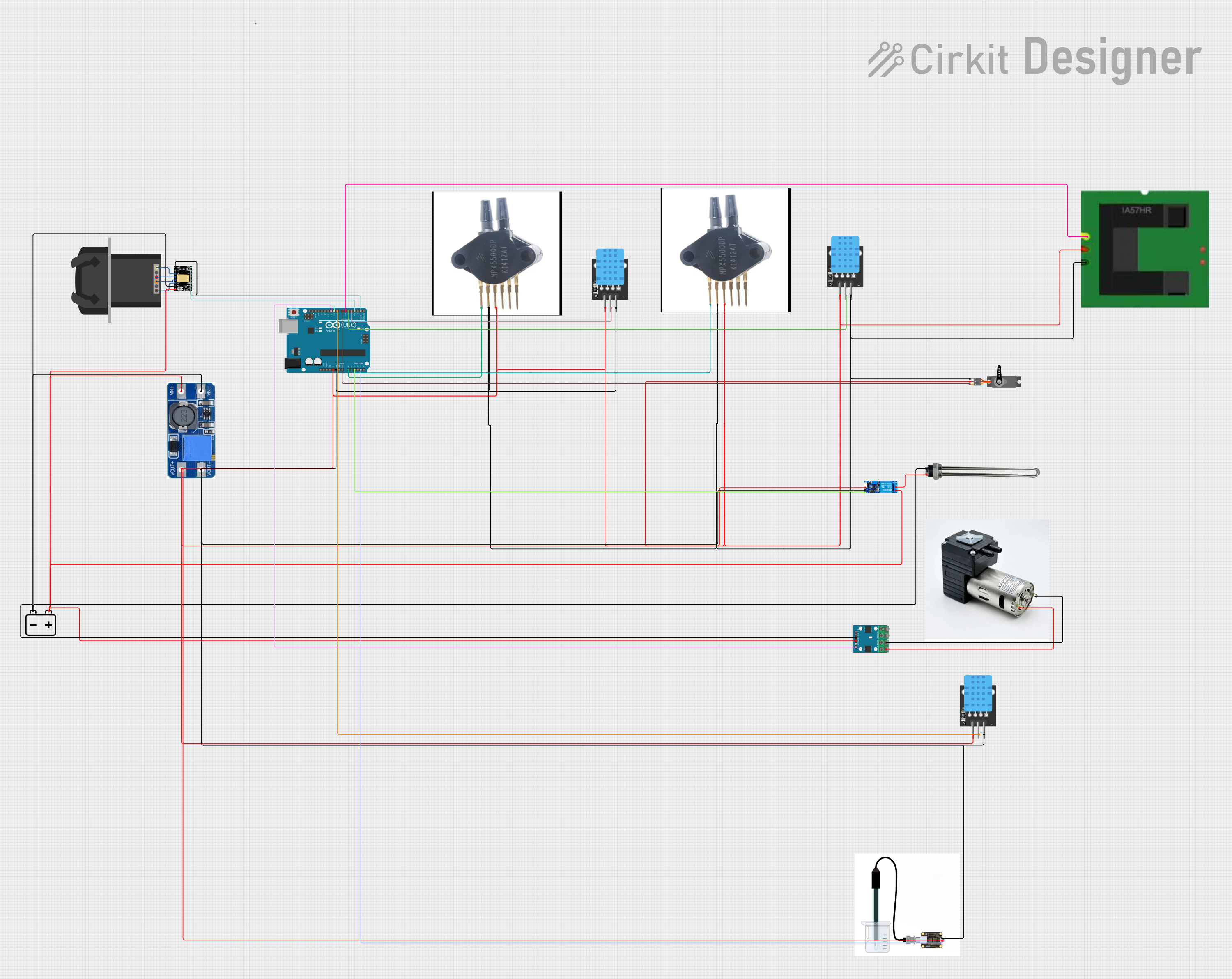 Open Project in Cirkit Designer
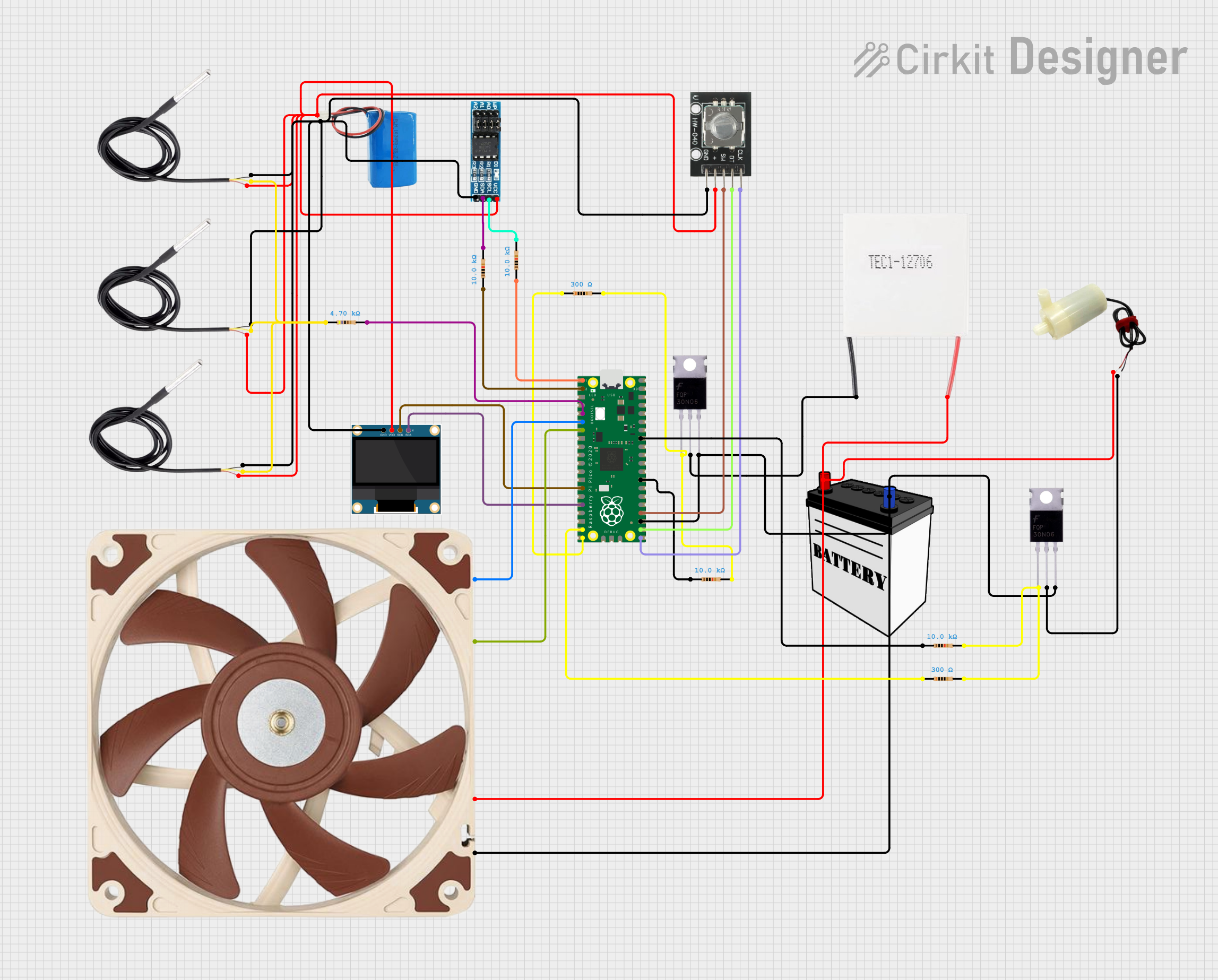 Open Project in Cirkit Designer
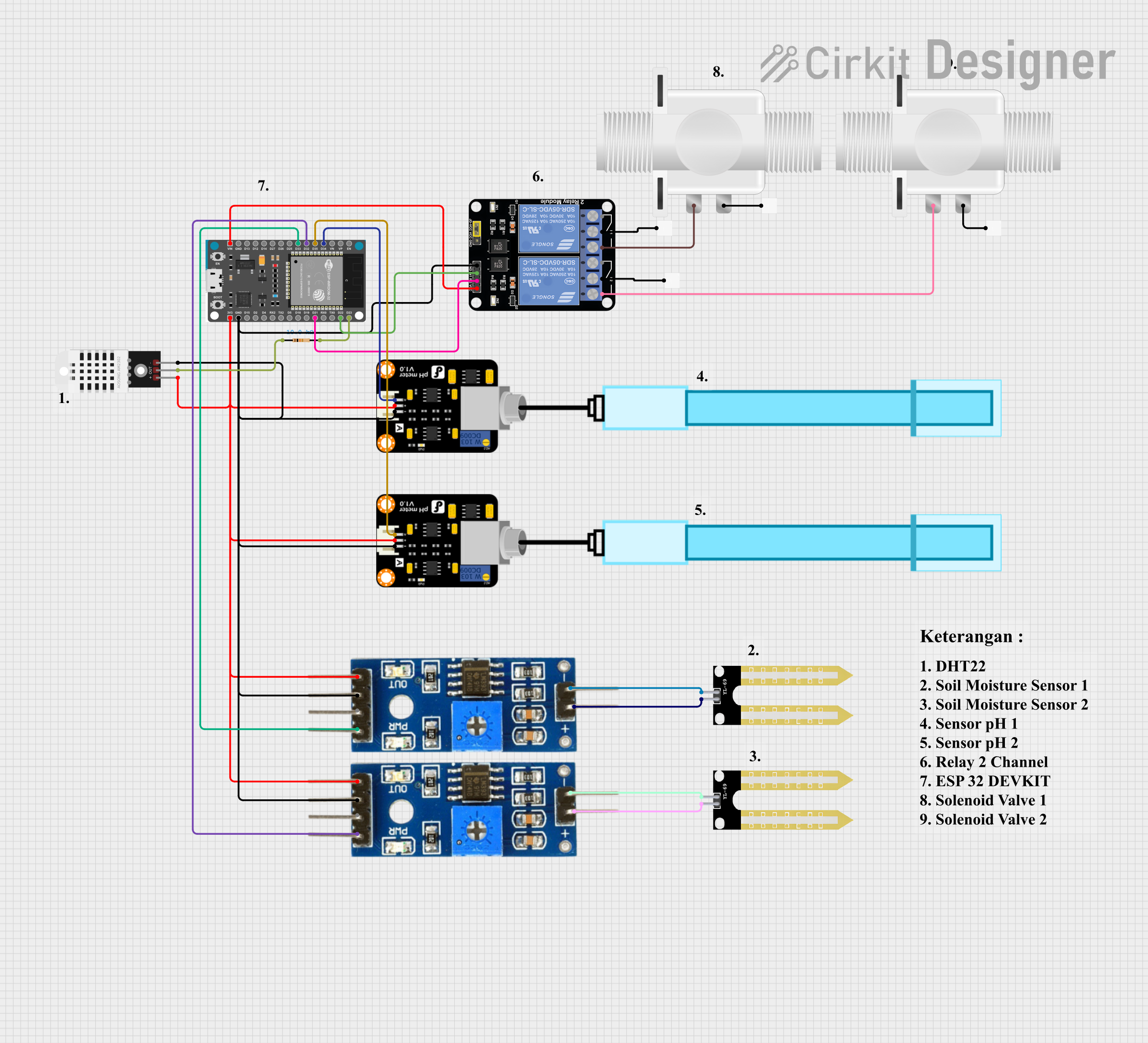 Open Project in Cirkit Designer
Explore Projects Built with PID Controller
Open Project in Cirkit DesignerOpen Project in Cirkit DesignerOpen Project in Cirkit DesignerOpen Project in Cirkit DesignerCommon Applications
- Temperature control in industrial ovens and furnaces
- Pressure regulation in hydraulic and pneumatic systems
- Flow rate control in chemical and fluid processing
- Speed control in motors and conveyor systems
- Humidity control in HVAC systems
Technical Specifications
The following table outlines the key technical details of the RS Pro 7983472 PID Controller:
| Parameter | Specification |
|---|---|
| Manufacturer | RS Pro |
| Part ID | 7983472 |
| Input Voltage | 100-240 VAC |
| Output Type | Relay, Voltage Pulse, or Current |
| Control Mode | PID, ON/OFF, Manual |
| Input Type | Thermocouple, RTD, Voltage, Current |
| Temperature Range | -10°C to 50°C |
| Accuracy | ±0.2% of full scale |
| Display | Dual 4-digit LED |
| Dimensions | 48 x 48 x 110 mm |
| Mounting | Panel-mounted |
Pin Configuration and Descriptions
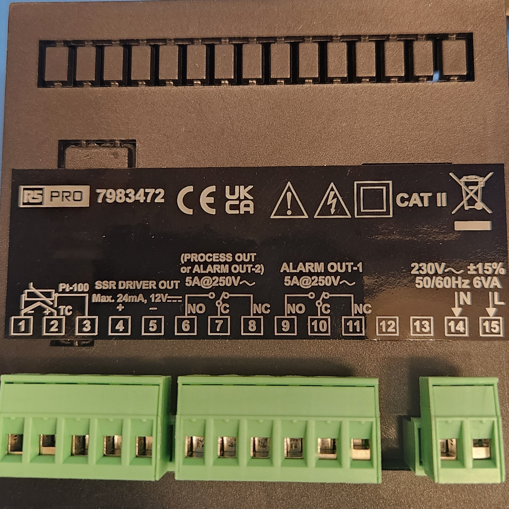
The RS Pro 7983472 PID Controller features a terminal block for wiring. Below is the pin configuration:
| Pin Number | Label | Description |
|---|---|---|
| 1 | L | Live AC input (100-240 VAC) |
| 2 | N | Neutral AC input |
| 3 | Input+ | Positive terminal for process variable input |
| 4 | Input- | Negative terminal for process variable input |
| 5 | Output+ | Positive terminal for control output |
| 6 | Output- | Negative terminal for control output |
| 7 | Alarm1 | Alarm output 1 |
| 8 | Alarm2 | Alarm output 2 |
| 9 | Ground | Earth connection |
Usage Instructions
How to Use the PID Controller in a Circuit
- Power Connection: Connect the live (L) and neutral (N) terminals to a 100-240 VAC power source.
- Input Signal: Connect the process variable sensor (e.g., thermocouple, RTD) to the Input+ and Input- terminals.
- Output Signal: Connect the control output terminals (Output+ and Output-) to the actuator or device being controlled (e.g., heater, motor).
- Alarm Outputs: If required, connect external alarm devices to Alarm1 and Alarm2 terminals.
- Grounding: Ensure the Ground terminal is properly connected to earth for safety.
Important Considerations
- Sensor Compatibility: Verify that the input sensor type (e.g., thermocouple, RTD) matches the controller's input configuration.
- Tuning Parameters: Adjust the proportional (P), integral (I), and derivative (D) parameters to optimize system performance. Start with default values and fine-tune as needed.
- Load Capacity: Ensure the connected load does not exceed the controller's output current or voltage rating.
- Environmental Conditions: Operate the controller within the specified temperature range (-10°C to 50°C) and avoid exposure to moisture or corrosive environments.
Example: Connecting to an Arduino UNO
The RS Pro 7983472 PID Controller can be interfaced with an Arduino UNO for advanced control and monitoring. Below is an example code snippet for reading the process variable and sending setpoints via serial communication:
#include <PID_v1.h> // Include the PID library

// Define PID parameters
double setpoint = 100.0; // Desired setpoint
double input = 0.0;      // Process variable (e.g., temperature)
double output = 0.0;     // PID output

// PID tuning parameters
double Kp = 2.0, Ki = 5.0, Kd = 1.0;

// Create PID object
PID myPID(&input, &output, &setpoint, Kp, Ki, Kd, DIRECT);

void setup() {
  Serial.begin(9600); // Initialize serial communication
  myPID.SetMode(AUTOMATIC); // Set PID to automatic mode
}

void loop() {
  // Simulate reading the process variable from the PID controller
  input = analogRead(A0) * (5.0 / 1023.0) * 100.0; // Example scaling

  // Compute PID output
  myPID.Compute();

  // Send the output to the actuator (e.g., PWM signal)
  analogWrite(9, output);

  // Print values for debugging
  Serial.print("Setpoint: ");
  Serial.print(setpoint);
  Serial.print(" Input: ");
  Serial.print(input);
  Serial.print(" Output: ");
  Serial.println(output);

  delay(100); // Delay for stability
}
Notes:
- Replace
analogRead(A0)with the actual input from the PID controller. - Adjust the
Kp,Ki, andKdvalues based on your system's requirements.
Troubleshooting and FAQs
Common Issues
No Display or Power:
- Cause: Incorrect wiring or no power supply.
- Solution: Verify the live (L) and neutral (N) connections and ensure the power source is active.
Inaccurate Readings:
- Cause: Incorrect sensor type or faulty sensor.
- Solution: Check the sensor type and wiring. Replace the sensor if necessary.
Unstable Control Output:
- Cause: Poorly tuned PID parameters.
- Solution: Adjust the proportional, integral, and derivative parameters to stabilize the system.
Alarm Triggering Unexpectedly:
- Cause: Alarm thresholds not configured correctly.
- Solution: Reconfigure the alarm settings in the controller menu.
FAQs
Q1: Can this PID controller handle multiple input types?
A1: Yes, the RS Pro 7983472 supports thermocouples, RTDs, voltage, and current inputs. Ensure the input type is configured correctly in the settings.
Q2: How do I reset the controller to factory settings?
A2: Refer to the user manual for the reset procedure. Typically, this involves navigating to the settings menu and selecting the reset option.
Q3: Can I use this controller for motor speed control?
A3: Yes, the controller can be used for motor speed control if the motor driver or actuator is compatible with the controller's output type.
Q4: What is the maximum load capacity for the output?
A4: The load capacity depends on the output type. Refer to the technical specifications for detailed ratings.
By following this documentation, users can effectively integrate and operate the RS Pro 7983472 PID Controller in their systems.