How to Use TPS61022: Examples, Pinouts, and Specs
Introduction
The TPS61022 is a high-efficiency boost converter manufactured by Anyone. It is designed to step up low input voltages to higher output voltages, making it ideal for battery-powered applications. With its wide input voltage range, adjustable output voltage, and compact package, the TPS61022 is a versatile solution for portable devices and other low-power systems.
Explore Projects Built with TPS61022


Explore Projects Built with TPS61022
Common Applications
- Battery-powered devices (e.g., wearables, IoT devices)
- Portable medical equipment
- Wireless sensors
- Handheld electronics
- Backup power systems
Technical Specifications
Key Technical Details
| Parameter | Value |
|---|---|
| Input Voltage Range | 0.5 V to 5.5 V |
| Output Voltage Range | 1.8 V to 5.5 V |
| Maximum Output Current | 5 A (depending on input/output conditions) |
| Efficiency | Up to 95% |
| Switching Frequency | 1 MHz |
| Quiescent Current | 26 µA |
| Package Type | 2.0 mm × 1.5 mm WSON-10 |
| Operating Temperature Range | -40°C to 125°C |
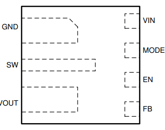
Pin Configuration and Descriptions
The TPS61022 is available in a 10-pin WSON package. Below is the pin configuration:
| Pin Number | Pin Name | Description |
|---|---|---|
| 1 | SW | Switch node. Connect to the inductor and diode. |
| 2 | VIN | Input voltage supply. Connect to the input power source. |
| 3 | EN | Enable pin. Drive high to enable the device, low to disable. |
| 4 | FB | Feedback pin. Connect to a resistor divider to set the output voltage. |
| 5 | GND | Ground. Connect to the system ground. |
| 6 | VOUT | Output voltage. Connect to the load and output capacitor. |
| 7 | PG | Power good indicator. Open-drain output, high when output is in regulation. |
| 8 | SS | Soft-start pin. Connect a capacitor to control startup timing. |
| 9 | COMP | Compensation pin. Connect to a capacitor and resistor for loop stability. |
| 10 | NC | No connection. Leave floating or connect to ground. |
Usage Instructions
How to Use the TPS61022 in a Circuit
Input and Output Capacitors:
- Place a low-ESR ceramic capacitor (e.g., 10 µF) close to the VIN pin to stabilize the input voltage.
- Use a similar capacitor (e.g., 22 µF) at the VOUT pin to stabilize the output voltage.
Inductor Selection:
- Choose an inductor with a saturation current higher than the peak current of the TPS61022.
- Typical inductance values range from 0.47 µH to 2.2 µH, depending on the application.
Feedback Resistor Divider:
- Use two resistors to set the output voltage. The formula is: [ V_{OUT} = V_{FB} \times \left(1 + \frac{R_1}{R_2}\right) ] where ( V_{FB} ) is typically 0.8 V.
Enable Pin:
- Drive the EN pin high (logic level 1) to enable the device. Pull it low to disable the device.
Soft-Start:
- Connect a capacitor to the SS pin to control the startup time. A larger capacitor results in a slower startup.
Power Good Indicator:
- Use the PG pin to monitor the output voltage. It is an open-drain output and requires a pull-up resistor.
Example Circuit
Below is a basic circuit diagram for the TPS61022:
VIN ----[10 µF]----+----[Inductor]----+---- VOUT
                   |                  |
                  GND                Load
Arduino UNO Example Code
The TPS61022 can be used with an Arduino UNO to control the enable pin. Below is an example code snippet:
// Define the enable pin for the TPS61022
const int enablePin = 7;

void setup() {
  // Set the enable pin as an output
  pinMode(enablePin, OUTPUT);

  // Enable the TPS61022 by setting the pin HIGH
  digitalWrite(enablePin, HIGH);

  // Optional: Add a delay to allow the boost converter to stabilize
  delay(100);
}

void loop() {
  // The TPS61022 remains enabled in this example
  // Add your application code here
}
Important Considerations
- Ensure the input voltage does not exceed the maximum rating of 5.5 V.
- Use proper PCB layout techniques to minimize noise and ensure stable operation.
- Place all external components (capacitors, resistors, inductor) as close to the IC as possible.
Troubleshooting and FAQs
Common Issues and Solutions
| Issue | Possible Cause | Solution |
|---|---|---|
| No output voltage | EN pin is not driven high | Check the EN pin connection and voltage. |
| Output voltage is unstable | Insufficient output capacitance | Increase the output capacitor value. |
| Device overheating | Inductor saturation or high load current | Use an inductor with higher saturation current. |
| Low efficiency | Incorrect component selection | Verify inductor and capacitor values. |
| PG pin not indicating "good" state | Output voltage not in regulation | Check the feedback resistor divider. |
FAQs
Can the TPS61022 operate with a single AA battery?
- Yes, the TPS61022 can operate with input voltages as low as 0.5 V, making it suitable for single-cell battery applications.
What is the maximum output current?
- The maximum output current is 5 A, but it depends on the input voltage, output voltage, and external components.
How do I calculate the soft-start time?
- The soft-start time is determined by the capacitor connected to the SS pin. Refer to the datasheet for the exact formula.
Can I leave the PG pin unconnected?
- Yes, the PG pin is optional. If unused, it can be left floating.
By following this documentation, users can effectively integrate the TPS61022 into their designs and troubleshoot common issues.