How to Use Siemens LOGO! POWER 24V 1,3A: Examples, Pinouts, and Specs
Introduction
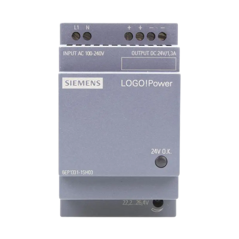
The Siemens LOGO! POWER 24V 1,3A is a compact and efficient power supply unit designed specifically for Siemens LOGO! programmable logic controllers (PLCs) and other automation devices. It provides a stable 24V DC output with a maximum current of 1.3A, making it ideal for powering small-scale industrial automation systems, control panels, and other low-power devices.
Explore Projects Built with Siemens LOGO! POWER 24V 1,3A


Explore Projects Built with Siemens LOGO! POWER 24V 1,3A
Common Applications and Use Cases
- Powering Siemens LOGO! PLCs in industrial automation systems
- Supplying 24V DC to sensors, relays, and actuators
- Use in control panels for building automation
- Applications requiring a reliable and compact DC power source
Technical Specifications
The Siemens LOGO! POWER 24V 1,3A is designed to meet the demands of industrial environments while maintaining high efficiency and reliability. Below are the key technical details:
Electrical Specifications
| Parameter | Value |
|---|---|
| Input Voltage Range | 100-240V AC (wide range) |
| Input Frequency | 50/60 Hz |
| Output Voltage | 24V DC |
| Output Current | 1.3A (maximum) |
| Efficiency | Up to 90% |
| Power Output | 31.2W |
| Ripple and Noise | < 150 mV |
| Overload Protection | Yes (automatic recovery) |
| Short-Circuit Protection | Yes |
Environmental Specifications
| Parameter | Value |
|---|---|
| Operating Temperature | -20°C to +70°C |
| Storage Temperature | -40°C to +85°C |
| Humidity Range | 5% to 95% (non-condensing) |
| Cooling Method | Natural convection |
| Mounting Type | DIN rail |
Pin Configuration and Descriptions
| Pin/Terminal | Description |
|---|---|
| L, N | AC input terminals (Line and Neutral) |
| +, - | DC output terminals (Positive and Negative) |
| PE | Protective Earth (ground connection) |
Usage Instructions
The Siemens LOGO! POWER 24V 1,3A is straightforward to use and can be easily integrated into automation systems. Follow the steps below to ensure proper operation:
Step-by-Step Instructions
Mounting the Power Supply:
- Securely mount the power supply on a DIN rail in a well-ventilated area.
- Ensure the ambient temperature does not exceed the specified operating range.
Connecting the Input:
- Connect the AC input terminals (L and N) to a 100-240V AC power source.
- Connect the PE terminal to the protective earth for safety.
Connecting the Output:
- Connect the + and - terminals to the load (e.g., Siemens LOGO! PLC or other devices).
- Ensure the total load does not exceed the maximum output current of 1.3A.
Powering On:
- Switch on the AC power source. The power supply will automatically regulate the output to 24V DC.
Verifying Operation:
- Use a multimeter to confirm the output voltage is 24V DC.
- Check that the connected devices are functioning correctly.
Important Considerations and Best Practices
- Load Capacity: Ensure the total load connected to the power supply does not exceed 1.3A to avoid overloading.
- Ventilation: Install the power supply in a location with adequate airflow to prevent overheating.
- Wiring: Use appropriately rated wires for both input and output connections to ensure safety and reliability.
- Protection: The power supply includes overload and short-circuit protection, but it is recommended to use external fuses or circuit breakers for additional safety.
Example: Connecting to an Arduino UNO
The Siemens LOGO! POWER 24V 1,3A can also be used to power an Arduino UNO with a step-down voltage regulator. Below is an example circuit and code:
Circuit Setup
- Connect the + and - terminals of the power supply to the input of a DC-DC step-down converter.
- Adjust the step-down converter to output 5V DC.
- Connect the 5V output of the converter to the Arduino UNO's 5V and GND pins.
Arduino Code Example
// Example code to blink an LED connected to pin 13 of the Arduino UNO
// Ensure the power supply is properly connected to the Arduino via a step-down converter

void setup() {
  pinMode(13, OUTPUT); // Set pin 13 as an output
}

void loop() {
  digitalWrite(13, HIGH); // Turn the LED on
  delay(1000);            // Wait for 1 second
  digitalWrite(13, LOW);  // Turn the LED off
  delay(1000);            // Wait for 1 second
}
Troubleshooting and FAQs
Common Issues and Solutions
No Output Voltage:
- Cause: AC input is not connected or is outside the specified range.
- Solution: Verify the AC input voltage and connections.
Overheating:
- Cause: Insufficient ventilation or excessive load.
- Solution: Ensure proper airflow and reduce the load to within the specified limit.
Output Voltage Fluctuations:
- Cause: Load exceeds the maximum current rating or input voltage is unstable.
- Solution: Reduce the load or stabilize the input voltage.
Short-Circuit Protection Triggered:
- Cause: Output terminals are shorted.
- Solution: Disconnect the load, resolve the short circuit, and reconnect.
FAQs
Q1: Can this power supply be used with devices other than Siemens LOGO! PLCs?
A1: Yes, it can power any device requiring 24V DC and up to 1.3A, provided the device is compatible with the power supply's specifications.
Q2: Is it safe to operate the power supply at maximum load continuously?
A2: Yes, the power supply is designed to handle continuous operation at 1.3A, but ensure proper ventilation to avoid overheating.
Q3: Can I use this power supply in outdoor environments?
A3: No, the power supply is not weatherproof. It should be installed in a dry, indoor environment.
Q4: What happens if the load exceeds 1.3A?
A4: The power supply's overload protection will activate, and the output will shut down temporarily. Reduce the load to restore normal operation.