Cirkit Designer Logo
Cirkit Designer
Your all-in-one circuit design IDE
Home / 
Component Documentation

How to Use Led Module Blue: Examples, Pinouts, and Specs

Image of Led Module Blue
Cirkit Designer LogoDesign with Led Module Blue in Cirkit Designer

Introduction

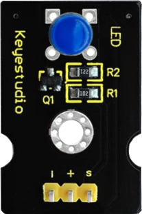
The Keyestudio LED Module Blue (Part ID: KS0232) is a compact and versatile module featuring a blue LED. It emits bright blue light when powered, making it ideal for a variety of applications. This module is commonly used as an indicator, in displays, or for decorative lighting in electronic projects. Its simple design and ease of use make it suitable for both beginners and experienced users.

Explore Projects Built with Led Module Blue

Use Cirkit Designer to design, explore, and prototype these projects online. Some projects support real-time simulation. Click "Open Project" to start designing instantly!
Blue LED Array Project
Image of FYP: A project utilizing Led Module Blue in a practical application
The circuit consists of two groups of four blue LEDs wired in parallel. Each group shares a common cathode and a common anode, indicating that they are likely to be controlled together. There are no microcontrollers or other control circuitry included in the provided information, suggesting that the LEDs are intended to be powered directly and will illuminate simultaneously when a voltage is applied across the common anode and cathode of each group.
Cirkit Designer LogoOpen Project in Cirkit Designer
Arduino Mega 2560 Bluetooth-Controlled LED Matrix Display with Servo Motor
Image of FYP: A project utilizing Led Module Blue in a practical application
This circuit features an Arduino Mega 2560 microcontroller that controls a 64x32 LED matrix display and a servo motor. It also includes an HC-05 Bluetooth module for wireless communication and a red LED with a current-limiting resistor. The Arduino is programmed to set a specific pin high, likely to control the LED.
Cirkit Designer LogoOpen Project in Cirkit Designer
Arduino UNO Bluetooth-Controlled LED System
Image of GROUP 2: A project utilizing Led Module Blue in a practical application
This circuit uses an Arduino UNO to control two LEDs (one blue and one green) via Bluetooth communication. An HC-05 Bluetooth module is connected to the Arduino, allowing it to receive commands to turn the LEDs on or off based on the received Bluetooth data.
Cirkit Designer LogoOpen Project in Cirkit Designer
Arduino Mega 2560 Controlled 12V Blue LED with Relay and LabVIEW Integration
Image of Led control with arduino: A project utilizing Led Module Blue in a practical application
This circuit uses a Mega 2560 R3 microcontroller to control a 12V Blue LED via a single-channel relay. The relay is powered by a 12V power supply and is controlled through pin D7 of the microcontroller, which toggles the LED on and off based on the microcontroller's output.
Cirkit Designer LogoOpen Project in Cirkit Designer

Explore Projects Built with Led Module Blue

Use Cirkit Designer to design, explore, and prototype these projects online. Some projects support real-time simulation. Click "Open Project" to start designing instantly!
Image of FYP: A project utilizing Led Module Blue in a practical application
Blue LED Array Project
The circuit consists of two groups of four blue LEDs wired in parallel. Each group shares a common cathode and a common anode, indicating that they are likely to be controlled together. There are no microcontrollers or other control circuitry included in the provided information, suggesting that the LEDs are intended to be powered directly and will illuminate simultaneously when a voltage is applied across the common anode and cathode of each group.
Cirkit Designer LogoOpen Project in Cirkit Designer
Image of FYP: A project utilizing Led Module Blue in a practical application
Arduino Mega 2560 Bluetooth-Controlled LED Matrix Display with Servo Motor
This circuit features an Arduino Mega 2560 microcontroller that controls a 64x32 LED matrix display and a servo motor. It also includes an HC-05 Bluetooth module for wireless communication and a red LED with a current-limiting resistor. The Arduino is programmed to set a specific pin high, likely to control the LED.
Cirkit Designer LogoOpen Project in Cirkit Designer
Image of GROUP 2: A project utilizing Led Module Blue in a practical application
Arduino UNO Bluetooth-Controlled LED System
This circuit uses an Arduino UNO to control two LEDs (one blue and one green) via Bluetooth communication. An HC-05 Bluetooth module is connected to the Arduino, allowing it to receive commands to turn the LEDs on or off based on the received Bluetooth data.
Cirkit Designer LogoOpen Project in Cirkit Designer
Image of Led control with arduino: A project utilizing Led Module Blue in a practical application
Arduino Mega 2560 Controlled 12V Blue LED with Relay and LabVIEW Integration
This circuit uses a Mega 2560 R3 microcontroller to control a 12V Blue LED via a single-channel relay. The relay is powered by a 12V power supply and is controlled through pin D7 of the microcontroller, which toggles the LED on and off based on the microcontroller's output.
Cirkit Designer LogoOpen Project in Cirkit Designer

Technical Specifications

The Keyestudio LED Module Blue is designed for low-power applications and is compatible with most microcontrollers, including Arduino boards. Below are the key technical details:

General Specifications

  • Manufacturer: Keyestudio
  • Part ID: KS0232
  • LED Color: Blue
  • Operating Voltage: 3.3V to 5V
  • Current Consumption: ~20mA
  • Dimensions: 18mm x 15mm x 8mm
  • Mounting Hole Diameter: 3mm

Pin Configuration and Descriptions

The module has three pins, as detailed in the table below:

Pin Label Description
1 S (Signal) Connects to the control signal (e.g., GPIO pin).
2 VCC Power supply pin (3.3V or 5V).
3 GND Ground connection.

Usage Instructions

How to Use the Component in a Circuit

  1. Powering the Module:
    Connect the VCC pin to a 3.3V or 5V power source and the GND pin to the ground of your circuit.

  2. Controlling the LED:
    Use the S (Signal) pin to control the LED. This pin can be connected to a GPIO pin of a microcontroller or directly to a power source for constant illumination. When the signal pin is HIGH, the LED will light up.

  3. Resistor Consideration:
    The module includes an onboard current-limiting resistor, so no external resistor is required when connecting it to a 5V source.

Example: Connecting to an Arduino UNO

Below is an example of how to connect and control the LED Module Blue using an Arduino UNO:

Circuit Connections

  • Connect the S pin of the module to digital pin 9 on the Arduino.
  • Connect the VCC pin to the 5V pin on the Arduino.
  • Connect the GND pin to the GND pin on the Arduino.

Arduino Code

// Example code to control the Keyestudio LED Module Blue (KS0232)

// Define the pin connected to the LED module
const int ledPin = 9;

void setup() {
  // Set the LED pin as an output
  pinMode(ledPin, OUTPUT);
}

void loop() {
  // Turn the LED on
  digitalWrite(ledPin, HIGH);
  delay(1000); // Wait for 1 second
  
  // Turn the LED off
  digitalWrite(ledPin, LOW);
  delay(1000); // Wait for 1 second
}

Important Considerations and Best Practices

  • Ensure the power supply voltage does not exceed 5V to avoid damaging the module.
  • Avoid connecting the S pin directly to a high-current source without a microcontroller or proper current-limiting circuitry.
  • For longer-lasting performance, avoid operating the LED at maximum brightness for extended periods.

Troubleshooting and FAQs

Common Issues and Solutions

  1. LED Does Not Light Up:

    • Cause: Incorrect wiring or insufficient power supply.
    • Solution: Double-check the connections and ensure the VCC and GND pins are properly connected to the power source.
  2. LED Flickers or Is Dim:

    • Cause: Insufficient current or loose connections.
    • Solution: Ensure the power supply can provide at least 20mA of current and check for secure connections.
  3. Module Overheats:

    • Cause: Excessive voltage or current.
    • Solution: Verify that the input voltage is within the 3.3V to 5V range.

FAQs

  • Q: Can I use this module with a 3.3V microcontroller?
    A: Yes, the module is compatible with both 3.3V and 5V systems.

  • Q: Do I need an external resistor for this module?
    A: No, the module includes an onboard current-limiting resistor.

  • Q: Can I use this module for PWM dimming?
    A: Yes, you can use a PWM signal on the S pin to control the brightness of the LED.

By following this documentation, you can effectively integrate the Keyestudio LED Module Blue (KS0232) into your projects and troubleshoot any issues that may arise.