Cirkit Designer Logo
Cirkit Designer
Your all-in-one circuit design IDE
Home / 
Component Documentation

How to Use Pololu - 0J10137: Examples, Pinouts, and Specs

Image of Pololu - 0J10137
Cirkit Designer LogoDesign with Pololu - 0J10137 in Cirkit Designer

Introduction

The Pololu 0J10137 is a compact, high-performance motor driver designed for controlling small DC motors and stepper motors. It features built-in protection mechanisms, including overcurrent and thermal overload protection, making it a reliable choice for a wide range of motor control applications. Its small form factor and robust design make it ideal for robotics, automation systems, and other projects requiring precise motor control.

Explore Projects Built with Pololu - 0J10137

Use Cirkit Designer to design, explore, and prototype these projects online. Some projects support real-time simulation. Click "Open Project" to start designing instantly!
Teensy 4.1-Based Multi-Channel Potentiometer Interface with 74HC4051 Mux and AMS1117 3.3V Regulator
Image of redrum: A project utilizing Pololu - 0J10137 in a practical application
This circuit features a Teensy 4.1 microcontroller interfaced with a SparkFun 74HC4051 8-channel multiplexer to read multiple rotary potentiometers. The AMS1117 3.3V voltage regulator provides a stable 3.3V supply to the multiplexer and potentiometers, while electrolytic and ceramic capacitors are used for power supply filtering and stabilization.
Cirkit Designer LogoOpen Project in Cirkit Designer
Arduino Mega 2560 Controlled Multi-Servo Random Positioning System
Image of robotic: A project utilizing Pololu - 0J10137 in a practical application
This circuit consists of an Arduino Mega 2560 microcontroller connected to twelve servo motors, each individually controlled by a distinct PWM pin on the Arduino. The servos are powered by a single Polymer Lithium Ion Battery, with all servos sharing a common power (VCC) and ground (GND) connection. The embedded code on the Arduino is designed to randomly position each servo within a 0 to 180-degree range, with a random delay between movements, demonstrating a multi-servo control system possibly for applications like robotics or animatronics.
Cirkit Designer LogoOpen Project in Cirkit Designer
Bluetooth-Controlled Robotic Vehicle with Arduino and Servo-Gearmotor Actuation
Image of CARM: A project utilizing Pololu - 0J10137 in a practical application
This circuit appears to be a remote-controlled robotic system with multiple servos and gearmotors, likely for movement and manipulation. An Arduino UNO microcontroller is used to control the servos and gearmotors via a L298N motor driver, and it interfaces with an HC-05 Bluetooth module for wireless communication. The system is powered by batteries, with a step-down converter to regulate voltage, and includes a relay and LED for power control and indication.
Cirkit Designer LogoOpen Project in Cirkit Designer
Mega2560-Controlled Automation System with Non-Contact Liquid Level Sensing and Motor Control
Image of Project_AutomaticBartender: A project utilizing Pololu - 0J10137 in a practical application
This circuit appears to be a complex control system centered around an Arduino Mega2560 R3 Pro microcontroller, which interfaces with multiple sensors (XKC-Y26-V non-contact liquid level sensors and an LM35 temperature sensor), servo motors, a touch display, and an IBT-2 H-Bridge motor driver for controlling a planetary gearbox motor. The system also includes a UART TTL to RS485 converter for communication, likely with the touch display, and a power management subsystem with a switching power supply, fuses, and circuit breakers for safety and voltage regulation (XL4016). The absence of embedded code suggests that the functionality of the microcontroller is not defined within the provided data.
Cirkit Designer LogoOpen Project in Cirkit Designer

Explore Projects Built with Pololu - 0J10137

Use Cirkit Designer to design, explore, and prototype these projects online. Some projects support real-time simulation. Click "Open Project" to start designing instantly!
Image of redrum: A project utilizing Pololu - 0J10137 in a practical application
Teensy 4.1-Based Multi-Channel Potentiometer Interface with 74HC4051 Mux and AMS1117 3.3V Regulator
This circuit features a Teensy 4.1 microcontroller interfaced with a SparkFun 74HC4051 8-channel multiplexer to read multiple rotary potentiometers. The AMS1117 3.3V voltage regulator provides a stable 3.3V supply to the multiplexer and potentiometers, while electrolytic and ceramic capacitors are used for power supply filtering and stabilization.
Cirkit Designer LogoOpen Project in Cirkit Designer
Image of robotic: A project utilizing Pololu - 0J10137 in a practical application
Arduino Mega 2560 Controlled Multi-Servo Random Positioning System
This circuit consists of an Arduino Mega 2560 microcontroller connected to twelve servo motors, each individually controlled by a distinct PWM pin on the Arduino. The servos are powered by a single Polymer Lithium Ion Battery, with all servos sharing a common power (VCC) and ground (GND) connection. The embedded code on the Arduino is designed to randomly position each servo within a 0 to 180-degree range, with a random delay between movements, demonstrating a multi-servo control system possibly for applications like robotics or animatronics.
Cirkit Designer LogoOpen Project in Cirkit Designer
Image of CARM: A project utilizing Pololu - 0J10137 in a practical application
Bluetooth-Controlled Robotic Vehicle with Arduino and Servo-Gearmotor Actuation
This circuit appears to be a remote-controlled robotic system with multiple servos and gearmotors, likely for movement and manipulation. An Arduino UNO microcontroller is used to control the servos and gearmotors via a L298N motor driver, and it interfaces with an HC-05 Bluetooth module for wireless communication. The system is powered by batteries, with a step-down converter to regulate voltage, and includes a relay and LED for power control and indication.
Cirkit Designer LogoOpen Project in Cirkit Designer
Image of Project_AutomaticBartender: A project utilizing Pololu - 0J10137 in a practical application
Mega2560-Controlled Automation System with Non-Contact Liquid Level Sensing and Motor Control
This circuit appears to be a complex control system centered around an Arduino Mega2560 R3 Pro microcontroller, which interfaces with multiple sensors (XKC-Y26-V non-contact liquid level sensors and an LM35 temperature sensor), servo motors, a touch display, and an IBT-2 H-Bridge motor driver for controlling a planetary gearbox motor. The system also includes a UART TTL to RS485 converter for communication, likely with the touch display, and a power management subsystem with a switching power supply, fuses, and circuit breakers for safety and voltage regulation (XL4016). The absence of embedded code suggests that the functionality of the microcontroller is not defined within the provided data.
Cirkit Designer LogoOpen Project in Cirkit Designer

Common Applications and Use Cases

  • Robotics and automation systems
  • Small DC motor control in hobbyist projects
  • Stepper motor control for 3D printers and CNC machines
  • Educational and prototyping purposes
  • Battery-powered motorized devices

Technical Specifications

The Pololu 0J10137 motor driver offers the following key technical specifications:

Parameter Value
Operating Voltage Range 4.5 V to 28 V
Continuous Output Current Up to 1.2 A per channel
Peak Output Current 2 A per channel (for short durations)
Control Interface PWM (Pulse Width Modulation)
Logic Voltage Range 2.5 V to 5.5 V
Built-in Protections Overcurrent, thermal shutdown, undervoltage
Dimensions 0.6" × 0.8" × 0.1" (15 mm × 20 mm × 3 mm)
Weight 1.2 g

Pin Configuration and Descriptions

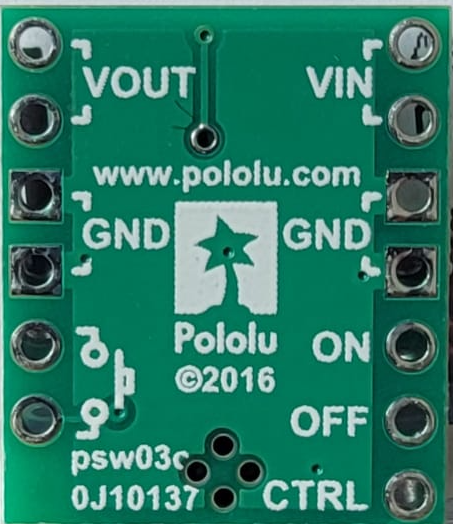
The Pololu 0J10137 has a simple pinout for easy integration into your circuit. Below is the pin configuration:

Pin Name Description
1 VIN Motor power supply input (4.5 V to 28 V).
2 GND Ground connection.
3 AIN1 Input control signal for motor channel A (logic high/low).
4 AIN2 Input control signal for motor channel A (logic high/low).
5 BIN1 Input control signal for motor channel B (logic high/low).
6 BIN2 Input control signal for motor channel B (logic high/low).
7 PWM PWM input for speed control (shared for both channels).
8 VOUT Motor output voltage (connect to motor terminals).

Usage Instructions

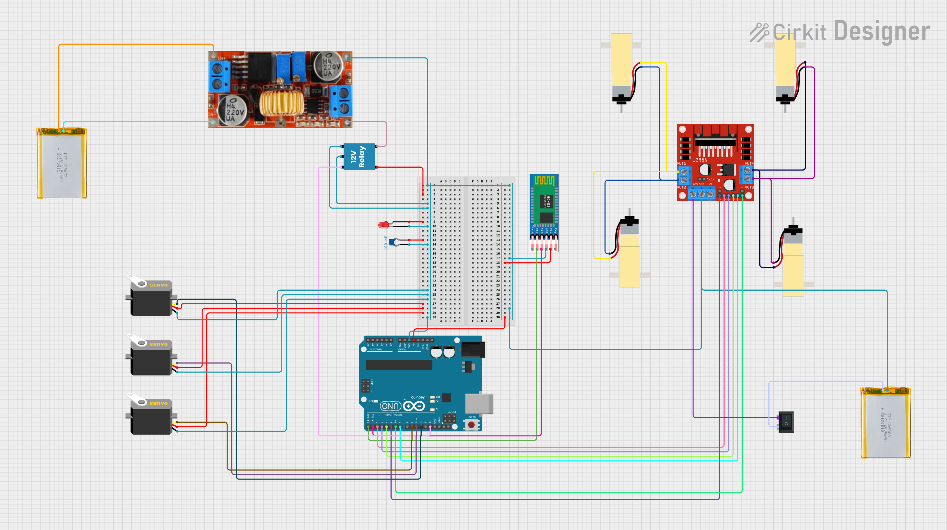
How to Use the Component in a Circuit

  1. Power Supply: Connect the VIN pin to a power source within the range of 4.5 V to 28 V. Ensure the power supply can provide sufficient current for your motor.
  2. Ground Connection: Connect the GND pin to the ground of your circuit.
  3. Motor Connections: Connect the motor terminals to the VOUT pins.
  4. Control Signals: Use the AIN1, AIN2, BIN1, and BIN2 pins to control the direction of the motors. Apply PWM signals to the PWM pin to control motor speed.
  5. Logic Voltage: Ensure the control signals are within the logic voltage range (2.5 V to 5.5 V).

Important Considerations and Best Practices

  • Heat Dissipation: The driver may heat up during operation. Ensure proper ventilation or use a heatsink if necessary.
  • Current Limiting: Avoid exceeding the peak current rating of 2 A per channel to prevent damage.
  • Decoupling Capacitors: Place a decoupling capacitor (e.g., 100 µF) across the VIN and GND pins to stabilize the power supply.
  • Motor Selection: Use motors that operate within the voltage and current limits of the driver.

Example Code for Arduino UNO

Below is an example of how to control a DC motor using the Pololu 0J10137 with an Arduino UNO:

// Define motor control pins
const int AIN1 = 3;  // Motor A control pin 1
const int AIN2 = 4;  // Motor A control pin 2
const int PWM = 5;   // PWM pin for speed control

void setup() {
  // Set motor control pins as outputs
  pinMode(AIN1, OUTPUT);
  pinMode(AIN2, OUTPUT);
  pinMode(PWM, OUTPUT);
}

void loop() {
  // Rotate motor forward
  digitalWrite(AIN1, HIGH);  // Set AIN1 high
  digitalWrite(AIN2, LOW);   // Set AIN2 low
  analogWrite(PWM, 128);     // Set speed to 50% (PWM value: 0-255)
  delay(2000);               // Run for 2 seconds

  // Rotate motor backward
  digitalWrite(AIN1, LOW);   // Set AIN1 low
  digitalWrite(AIN2, HIGH);  // Set AIN2 high
  analogWrite(PWM, 128);     // Set speed to 50%
  delay(2000);               // Run for 2 seconds

  // Stop motor
  digitalWrite(AIN1, LOW);   // Set AIN1 low
  digitalWrite(AIN2, LOW);   // Set AIN2 low
  analogWrite(PWM, 0);       // Set speed to 0%
  delay(2000);               // Stop for 2 seconds
}

Troubleshooting and FAQs

Common Issues and Solutions

  1. Motor Not Spinning:

    • Ensure the power supply is connected and within the specified voltage range.
    • Verify that the control signals (AIN1, AIN2, BIN1, BIN2) are correctly configured.
    • Check for loose or incorrect wiring.
  2. Overheating:

    • Ensure the motor driver is not exceeding its current or voltage limits.
    • Improve ventilation or add a heatsink to dissipate heat.
  3. Erratic Motor Behavior:

    • Check for noise or instability in the power supply. Add a decoupling capacitor if needed.
    • Verify that the PWM signal is stable and within the correct frequency range.
  4. Driver Shutting Down:

    • This may be due to thermal or overcurrent protection. Reduce the load on the motor or improve cooling.

FAQs

Q: Can I use this driver for stepper motors?
A: Yes, the Pololu 0J10137 can control stepper motors. Use both channels (A and B) to drive the two coils of the stepper motor.

Q: What is the recommended PWM frequency?
A: A PWM frequency between 20 kHz and 50 kHz is recommended for optimal performance.

Q: Can I use this driver with a 3.3 V microcontroller?
A: Yes, the driver supports logic voltages as low as 2.5 V, making it compatible with 3.3 V systems.

Q: Is reverse polarity protection included?
A: No, the driver does not have reverse polarity protection. Ensure correct polarity when connecting the power supply.