How to Use USB 2.0 Female Header: Examples, Pinouts, and Specs
Introduction
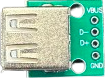
The USB 2.0 Female Header is a connector designed to provide a female interface for USB cables, enabling USB 2.0 devices to connect to a circuit board. It is widely used in embedded systems, development boards, and custom electronics projects to facilitate data transfer and power delivery. This component adheres to the USB 2.0 standard, supporting data transfer rates of up to 480 Mbps.
Explore Projects Built with USB 2.0 Female Header


Explore Projects Built with USB 2.0 Female Header
Common Applications and Use Cases
- Connecting USB peripherals (e.g., keyboards, mice, flash drives) to embedded systems.
- Providing USB connectivity in custom PCB designs.
- Enabling firmware updates or data transfer in microcontroller-based projects.
- Powering low-power USB devices.
Technical Specifications
The USB 2.0 Female Header is designed to meet the USB 2.0 standard and has the following key specifications:
| Parameter | Value |
|---|---|
| Standard | USB 2.0 |
| Data Transfer Rate | Up to 480 Mbps |
| Voltage Rating | 5V DC |
| Current Rating | 1A (maximum) |
| Operating Temperature | -20°C to 85°C |
| Connector Type | Female |
| Mounting Type | Through-hole or surface-mount |
| Pin Count | 4 pins (VCC, D-, D+, GND) |
Pin Configuration and Descriptions
The USB 2.0 Female Header has four pins, as described in the table below:
| Pin Number | Name | Description |
|---|---|---|
| 1 | VCC | Power supply pin (5V DC). Provides power to the USB device. |
| 2 | D- | Data line for differential signaling (negative). |
| 3 | D+ | Data line for differential signaling (positive). |
| 4 | GND | Ground connection. |
Usage Instructions
How to Use the USB 2.0 Female Header in a Circuit
Mounting the Header:
- Solder the USB 2.0 Female Header onto the PCB using the through-hole or surface-mount pads.
- Ensure proper alignment of the pins to avoid misconnection.
Connecting to a Microcontroller:
- Connect the
VCCpin to a 5V power source. - Connect the
GNDpin to the ground of the circuit. - Connect the
D-andD+pins to the corresponding data lines of the microcontroller or USB controller.
- Connect the
Power and Data Considerations:
- Ensure the power supply can handle the current requirements of the connected USB device.
- Use proper decoupling capacitors near the VCC pin to reduce noise.
Testing the Connection:
- Plug a USB device into the female header and verify that it powers on.
- Test data transfer functionality using a USB-enabled microcontroller or development board.
Important Considerations and Best Practices
- Signal Integrity: Keep the D- and D+ traces as short and parallel as possible to maintain signal integrity.
- ESD Protection: Add ESD protection diodes on the D- and D+ lines to protect the circuit from electrostatic discharge.
- Power Supply: Ensure the power supply is stable and capable of delivering sufficient current for the connected USB device.
- Compliance: Follow USB 2.0 design guidelines to ensure compatibility with USB devices.
Example: Connecting to an Arduino UNO
The USB 2.0 Female Header can be used to interface USB devices with an Arduino UNO. Below is an example of how to connect the header and read data from a USB device.
Circuit Diagram
- Connect the
VCCpin of the header to the 5V pin on the Arduino. - Connect the
GNDpin of the header to the GND pin on the Arduino. - Use a USB-to-serial converter IC (e.g., FT232) to interface the D- and D+ lines with the Arduino.
Sample Code
#include <SoftwareSerial.h>

// Define RX and TX pins for software serial communication
SoftwareSerial usbSerial(10, 11); // RX = pin 10, TX = pin 11

void setup() {
  // Initialize serial communication
  Serial.begin(9600); // For debugging via the Arduino Serial Monitor
  usbSerial.begin(9600); // For communication with the USB device

  Serial.println("USB 2.0 Female Header Test");
}

void loop() {
  // Check if data is available from the USB device
  if (usbSerial.available()) {
    char data = usbSerial.read(); // Read a byte of data
    Serial.print("Received: ");
    Serial.println(data); // Print the received data to the Serial Monitor
  }

  // Optional: Send data to the USB device
  if (Serial.available()) {
    char data = Serial.read(); // Read a byte from the Serial Monitor
    usbSerial.write(data); // Send the byte to the USB device
  }
}
Note: The above code assumes the use of a USB-to-serial converter IC to handle USB communication. Directly connecting D- and D+ to the Arduino pins is not recommended.
Troubleshooting and FAQs
Common Issues and Solutions
USB Device Not Recognized:
- Cause: Incorrect wiring or insufficient power supply.
- Solution: Double-check the connections and ensure the power supply meets the device's requirements.
Data Transfer Errors:
- Cause: Poor signal integrity due to long or improperly routed D- and D+ traces.
- Solution: Shorten the traces and route them as a differential pair.
Overheating:
- Cause: Excessive current draw from the USB device.
- Solution: Use a current-limiting circuit or ensure the power supply can handle the load.
No Power to USB Device:
- Cause: VCC or GND not connected properly.
- Solution: Verify the solder joints and connections to the power supply.
FAQs
Q1: Can the USB 2.0 Female Header be used with USB 3.0 devices?
A1: Yes, USB 3.0 devices are backward compatible with USB 2.0, but the data transfer rate will be limited to 480 Mbps.
Q2: What is the maximum cable length supported by USB 2.0?
A2: The maximum recommended cable length for USB 2.0 is 5 meters to maintain signal integrity.
Q3: Do I need additional components to use this header?
A3: For basic power delivery, no additional components are needed. For data transfer, you may need a USB controller or USB-to-serial converter IC.
Q4: Can I use this header for charging devices?
A4: Yes, as long as the power supply can provide sufficient current for the device being charged.