How to Use Flame Sensor: Examples, Pinouts, and Specs

Introduction
The flame sensor is an electronic component designed to detect the presence of fire or flames by sensing the infrared (IR) radiation emitted by the flame. It is commonly used in safety systems to trigger alarms, shut down equipment, or activate fire suppression systems. Flame sensors are highly sensitive to IR wavelengths typically emitted by flames, making them ideal for fire detection in industrial, commercial, and residential applications.
Explore Projects Built with Flame Sensor
Explore Projects Built with Flame Sensor
Common Applications and Use Cases
- Fire detection systems in industrial and residential settings
- Gas stove or furnace flame monitoring
- Firefighting robots and autonomous systems
- Safety mechanisms in boilers and heating systems
- Early warning systems for fire hazards
Technical Specifications
Below are the key technical details of a typical flame sensor module:
| Parameter | Value |
|---|---|
| Operating Voltage | 3.3V to 5V |
| Current Consumption | 20mA (typical) |
| Detection Angle | 60° |
| Spectral Range | 760 nm to 1100 nm (IR wavelength) |
| Output Type | Digital (D0) and Analog (A0) |
| Response Time | ≤ 15 ms |
| Operating Temperature | -25°C to +85°C |
Pin Configuration and Descriptions
The flame sensor module typically has three or four pins. Below is the pinout description:
| Pin | Name | Description |
|---|---|---|
| 1 | VCC | Power supply pin. Connect to 3.3V or 5V. |
| 2 | GND | Ground pin. Connect to the ground of the circuit. |
| 3 | D0 | Digital output pin. Outputs HIGH (1) when flame is detected, LOW (0) otherwise. |
| 4 | A0 (optional) | Analog output pin. Outputs a voltage proportional to the intensity of the flame. |
Usage Instructions
How to Use the Flame Sensor in a Circuit
- Power the Sensor: Connect the VCC pin to a 3.3V or 5V power source and the GND pin to the ground.
- Choose Output Type:
- Use the D0 pin for digital output. This pin outputs HIGH (1) when a flame is detected and LOW (0) otherwise.
- Use the A0 pin for analog output. This pin provides a voltage proportional to the intensity of the detected flame.
- Adjust Sensitivity: The module typically includes a potentiometer to adjust the sensitivity of the digital output. Rotate the potentiometer clockwise or counterclockwise to fine-tune the detection threshold.
- Connect to a Microcontroller: Connect the output pins (D0 or A0) to the corresponding input pins of a microcontroller (e.g., Arduino UNO) for further processing.
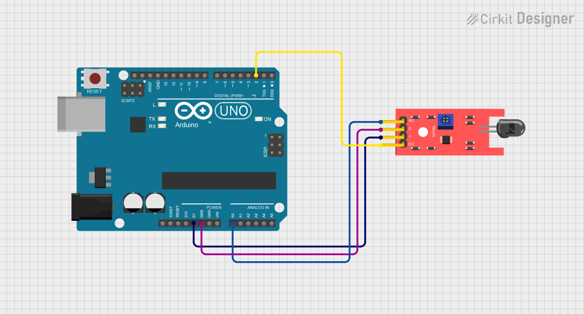
Example: Connecting to an Arduino UNO
Below is an example of how to connect and use the flame sensor with an Arduino UNO:
Circuit Connections
- Connect the VCC pin of the flame sensor to the 5V pin on the Arduino.
- Connect the GND pin of the flame sensor to the GND pin on the Arduino.
- Connect the D0 pin of the flame sensor to digital pin 2 on the Arduino.
Arduino Code Example
// Flame Sensor Example Code
// This code reads the digital output of the flame sensor and turns on an LED
// when a flame is detected.

const int flameSensorPin = 2; // Digital pin connected to D0 of the flame sensor
const int ledPin = 13;        // Built-in LED pin on Arduino

void setup() {
  pinMode(flameSensorPin, INPUT); // Set flame sensor pin as input
  pinMode(ledPin, OUTPUT);        // Set LED pin as output
  Serial.begin(9600);             // Initialize serial communication
}

void loop() {
  int flameDetected = digitalRead(flameSensorPin); // Read the flame sensor output

  if (flameDetected == HIGH) {
    // Flame detected
    digitalWrite(ledPin, HIGH); // Turn on the LED
    Serial.println("Flame detected!");
  } else {
    // No flame detected
    digitalWrite(ledPin, LOW);  // Turn off the LED
    Serial.println("No flame detected.");
  }

  delay(500); // Wait for 500ms before the next reading
}
Important Considerations and Best Practices
- Avoid Direct Sunlight: The flame sensor is sensitive to IR radiation, so avoid placing it in direct sunlight or near other strong IR sources.
- Optimal Placement: Position the sensor at an angle where it has a clear line of sight to the flame for accurate detection.
- Sensitivity Adjustment: Use the onboard potentiometer to adjust the sensitivity based on the application requirements.
- Power Supply: Ensure a stable power supply to avoid false readings.
Troubleshooting and FAQs
Common Issues and Solutions
False Positives (Flame Detected When None is Present):
- Ensure the sensor is not exposed to strong IR sources like sunlight or incandescent bulbs.
- Adjust the sensitivity using the potentiometer.
No Detection of Flame:
- Verify the connections and ensure the sensor is powered correctly.
- Check the detection angle and ensure the flame is within the sensor's field of view.
- Increase the sensitivity using the potentiometer.
Unstable or Fluctuating Readings:
- Use a decoupling capacitor (e.g., 0.1 µF) across the power supply pins to stabilize the voltage.
- Ensure the sensor is not exposed to electrical noise or interference.
FAQs
Q: Can the flame sensor detect all types of flames?
A: The flame sensor is most sensitive to flames that emit IR radiation, such as those from gas or alcohol-based fires. It may not detect flames that emit little to no IR radiation.
Q: Can I use the flame sensor outdoors?
A: While the sensor can be used outdoors, it should be shielded from direct sunlight and weather conditions to ensure accurate readings.
Q: What is the maximum distance for flame detection?
A: The detection range depends on the intensity of the flame and the sensitivity setting. Typically, it can detect flames up to 1 meter away under optimal conditions.
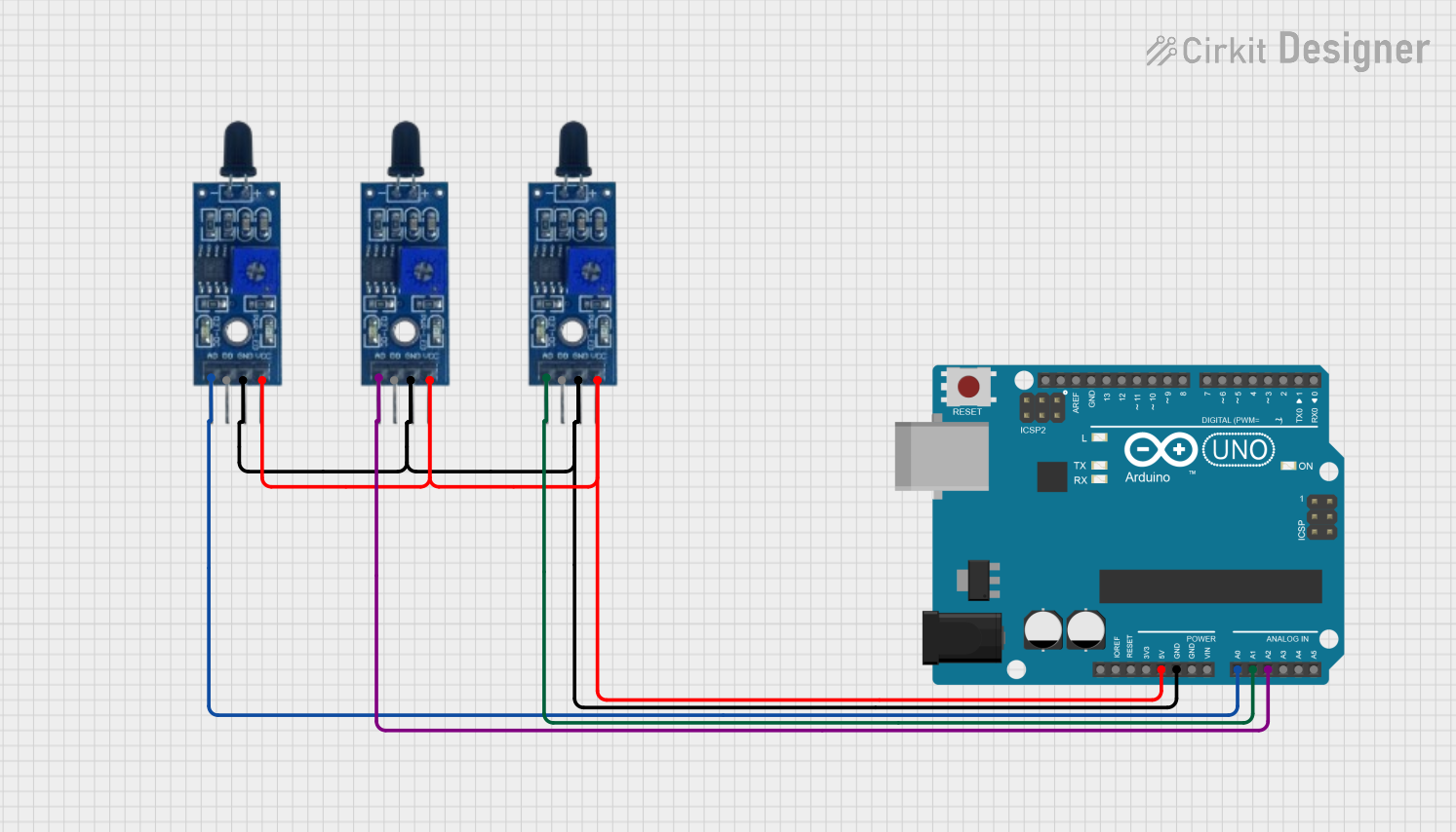
Q: Can I use multiple flame sensors in a single system?
A: Yes, multiple sensors can be used to cover a larger area or detect flames from different angles. Ensure each sensor is properly connected and calibrated.