
How to Use Charger + Boost Converter DD05CVSA: Examples, Pinouts, and Specs
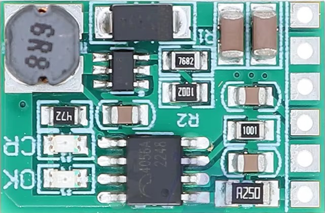
 Design with Charger + Boost Converter DD05CVSA in Cirkit Designer
Introduction
The Charger + Boost Converter DD05CVSA is a versatile and compact electronic module that integrates two essential functionalities: battery charging and voltage boosting. This device is designed to charge lithium-ion or lithium-polymer batteries efficiently while simultaneously stepping up the output voltage to a user-defined level. Its dual functionality makes it an excellent choice for portable electronics, DIY projects, and battery-powered systems.
Explore Projects Built with Charger + Boost Converter DD05CVSA
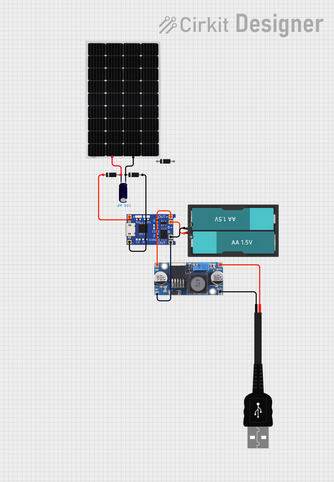 Open Project in Cirkit Designer
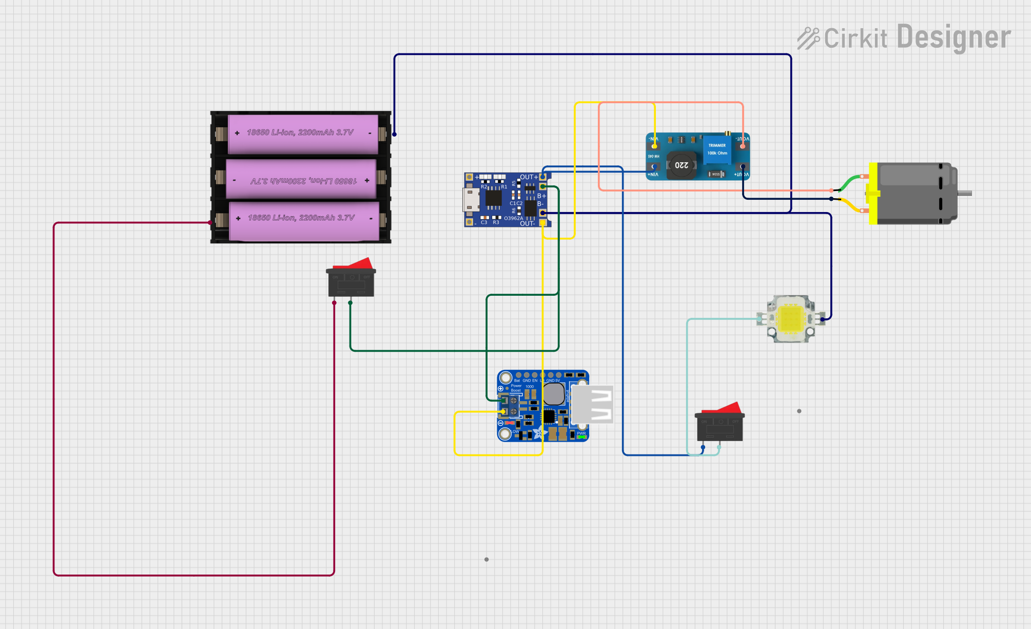 Open Project in Cirkit Designer
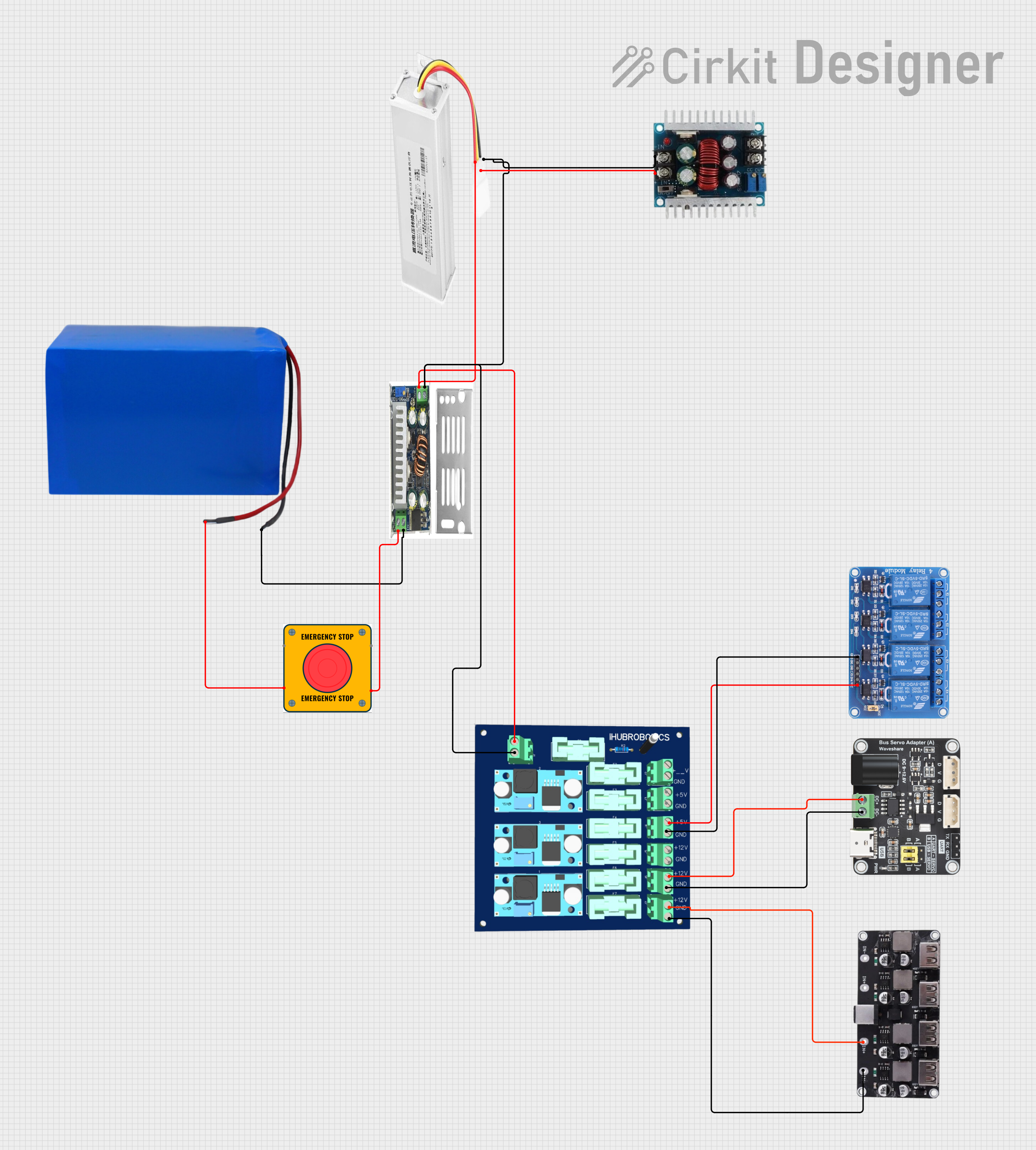 Open Project in Cirkit Designer
 Open Project in Cirkit Designer
Explore Projects Built with Charger + Boost Converter DD05CVSA
Open Project in Cirkit DesignerOpen Project in Cirkit DesignerOpen Project in Cirkit DesignerOpen Project in Cirkit DesignerCommon Applications and Use Cases
- Powering portable devices such as LED lights, small motors, or microcontrollers.
- DIY projects requiring a stable boosted voltage from a single battery source.
- Battery-powered systems where charging and voltage regulation are needed.
- Emergency power banks or backup power supplies.
Technical Specifications
The following table outlines the key technical details of the DD05CVSA module:
| Parameter | Value |
|---|---|
| Input Voltage Range | 2.5V to 5.5V |
| Output Voltage Range | Adjustable, 4.5V to 9V (via potentiometer) |
| Maximum Output Current | 1A (depends on input voltage and load) |
| Charging Current | 1A (constant current mode) |
| Battery Type Supported | Lithium-ion or Lithium-polymer (3.7V) |
| Efficiency | Up to 92% |
| Dimensions | 22mm x 17mm x 4mm |
Pin Configuration and Descriptions
The DD05CVSA module has the following pinout:
| Pin Name | Description |
|---|---|
| IN+ | Positive input terminal for the power source (e.g., USB or DC supply). |
| IN- | Negative input terminal (ground) for the power source. |
| BAT+ | Positive terminal for connecting the battery. |
| BAT- | Negative terminal for connecting the battery (ground). |
| OUT+ | Positive output terminal for the boosted voltage. |
| OUT- | Negative output terminal for the boosted voltage (ground). |
Usage Instructions
How to Use the Component in a Circuit
- Power Input: Connect a power source (e.g., USB or DC supply) to the
IN+andIN-pins. Ensure the input voltage is within the range of 2.5V to 5.5V. - Battery Connection: Attach a 3.7V lithium-ion or lithium-polymer battery to the
BAT+andBAT-pins. Ensure correct polarity to avoid damage. - Output Voltage Adjustment: Use the onboard potentiometer to adjust the output voltage. Turn the potentiometer clockwise to increase the voltage and counterclockwise to decrease it. The output voltage can be measured across the
OUT+andOUT-pins. - Load Connection: Connect your load (e.g., microcontroller, LED, or motor) to the
OUT+andOUT-pins. Ensure the load does not exceed the maximum output current of 1A.
Important Considerations and Best Practices
- Heat Dissipation: The module may heat up under high current loads. Ensure proper ventilation or add a heatsink if necessary.
- Battery Protection: Use a battery with built-in protection circuitry to prevent overcharging, over-discharging, or short circuits.
- Voltage Adjustment: Always measure the output voltage with a multimeter after adjusting the potentiometer to ensure it matches your requirements.
- Input Voltage: Do not exceed the maximum input voltage of 5.5V to avoid damaging the module.
Example: Using with an Arduino UNO
The DD05CVSA can be used to power an Arduino UNO by boosting the voltage from a 3.7V lithium-ion battery to 5V. Below is an example circuit and Arduino code:
Circuit Connections
- Connect the
BAT+andBAT-pins to a 3.7V lithium-ion battery. - Adjust the output voltage to 5V using the potentiometer.
- Connect the
OUT+pin to the Arduino UNO's5Vpin. - Connect the
OUT-pin to the Arduino UNO'sGNDpin.
Arduino Code Example
// Example code to blink an LED connected to pin 13 on the Arduino UNO
// Ensure the DD05CVSA module is providing a stable 5V to the Arduino UNO.

void setup() {
  pinMode(13, OUTPUT); // Set pin 13 as an output pin
}

void loop() {
  digitalWrite(13, HIGH); // Turn the LED on
  delay(1000);            // Wait for 1 second
  digitalWrite(13, LOW);  // Turn the LED off
  delay(1000);            // Wait for 1 second
}
Troubleshooting and FAQs
Common Issues and Solutions
Module Overheating:
- Cause: High current load or insufficient ventilation.
- Solution: Reduce the load current or add a heatsink to the module.
No Output Voltage:
- Cause: Incorrect connections or damaged module.
- Solution: Verify all connections and ensure the input voltage is within the specified range. Check for any visible damage to the module.
Battery Not Charging:
- Cause: Incorrect battery connection or unsupported battery type.
- Solution: Ensure the battery is connected with the correct polarity and is a 3.7V lithium-ion or lithium-polymer type.
Output Voltage Fluctuations:
- Cause: Unstable input voltage or excessive load.
- Solution: Use a stable power source and ensure the load does not exceed 1A.
FAQs
Q: Can I use this module with a NiMH or lead-acid battery?
A: No, the DD05CVSA is designed specifically for 3.7V lithium-ion or lithium-polymer batteries.
Q: How do I know if the battery is fully charged?
A: The module does not have an onboard indicator for full charge. Use a multimeter to monitor the battery voltage (typically 4.2V for a fully charged lithium-ion battery).
Q: Can I use this module to power a Raspberry Pi?
A: While the module can provide 5V output, the Raspberry Pi's current requirements may exceed the module's 1A limit, especially under heavy loads. Use with caution.
Q: Is reverse polarity protection included?
A: No, the module does not have reverse polarity protection. Always double-check connections before powering the module.