
How to Use RFM22: Examples, Pinouts, and Specs

 Design with RFM22 in Cirkit Designer
Introduction
The RFM22 is a low-power, high-performance transceiver module designed for wireless communication in the 433 MHz, 868 MHz, and 915 MHz frequency bands. It supports multiple modulation schemes, including FSK, GFSK, and OOK, making it versatile for a wide range of applications. The RFM22 is commonly used in remote control systems, wireless sensor networks, telemetry, and other low-power wireless communication systems. Its compact size and robust features make it an excellent choice for both hobbyists and professional engineers.
Explore Projects Built with RFM22
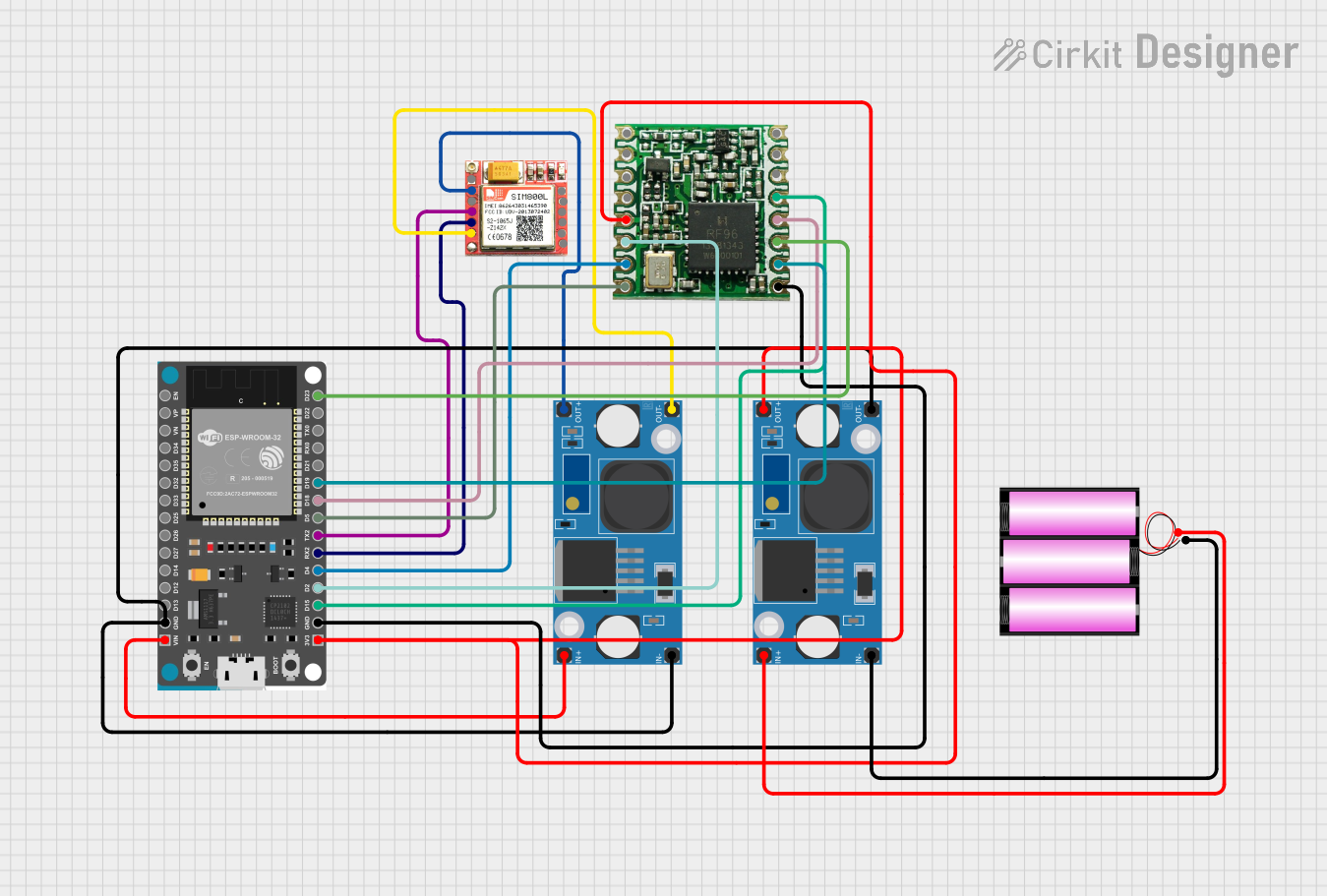 Open Project in Cirkit Designer
 Open Project in Cirkit Designer
 Open Project in Cirkit Designer
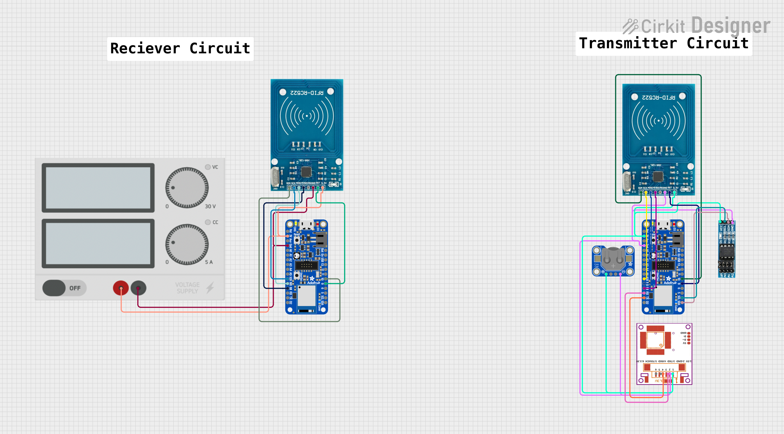 Open Project in Cirkit Designer
Explore Projects Built with RFM22
Open Project in Cirkit DesignerOpen Project in Cirkit DesignerOpen Project in Cirkit DesignerOpen Project in Cirkit DesignerTechnical Specifications
Below are the key technical details of the RFM22 transceiver module:
- Frequency Range: 433 MHz, 868 MHz, 915 MHz
- Modulation Schemes: FSK, GFSK, OOK
- Data Rate: 0.123 kbps to 256 kbps
- Output Power: Up to +20 dBm
- Supply Voltage: 1.8V to 3.6V
- Current Consumption:
- Transmit: 85 mA (at +20 dBm)
- Receive: 18.5 mA
- Standby: 1.2 µA
- Operating Temperature: -40°C to +85°C
- Interface: SPI (Serial Peripheral Interface)
- Antenna Interface: 50 Ω impedance
Pin Configuration and Descriptions
The RFM22 module has 16 pins. Below is the pinout and description:
| Pin Number | Pin Name | Description |
|---|---|---|
| 1 | GND | Ground connection |
| 2 | ANT | Antenna connection (50 Ω impedance) |
| 3 | VDD | Power supply input (1.8V to 3.6V) |
| 4 | SDN | Shutdown pin (active high) |
| 5 | GPIO0 | General-purpose I/O pin 0 |
| 6 | GPIO1 | General-purpose I/O pin 1 |
| 7 | GPIO2 | General-purpose I/O pin 2 |
| 8 | GPIO3 | General-purpose I/O pin 3 |
| 9 | SDO | SPI data output |
| 10 | SDI | SPI data input |
| 11 | SCLK | SPI clock input |
| 12 | nSEL | SPI chip select (active low) |
| 13 | nIRQ | Interrupt request output (active low) |
| 14 | TX State | Transmit state indicator |
| 15 | RX State | Receive state indicator |
| 16 | GND | Ground connection |
Usage Instructions
How to Use the RFM22 in a Circuit
- Power Supply: Connect the VDD pin to a regulated power supply (1.8V to 3.6V). Ensure proper decoupling capacitors are placed near the VDD pin to reduce noise.
- Antenna: Attach a 50 Ω antenna to the ANT pin for optimal wireless communication.
- SPI Interface: Connect the SPI pins (SDO, SDI, SCLK, and nSEL) to the microcontroller's SPI interface. Ensure the SPI clock speed is compatible with the RFM22.
- GPIO Pins: Configure the GPIO pins as needed for your application. These can be used for additional control or status monitoring.
- Shutdown Pin: Use the SDN pin to enable or disable the module. Pull this pin high to shut down the module and low to enable it.
- Interrupts: Use the nIRQ pin to handle interrupts for events such as packet reception or transmission completion.
Important Considerations and Best Practices
- Antenna Design: Use a properly tuned antenna for the frequency band you are operating in (433 MHz, 868 MHz, or 915 MHz). Poor antenna design can significantly reduce range and performance.
- Power Supply Filtering: Use low ESR capacitors for decoupling to ensure stable operation and minimize noise.
- SPI Communication: Ensure proper timing and configuration of the SPI interface. The RFM22 operates in SPI mode 0 (CPOL = 0, CPHA = 0).
- Firmware Configuration: Configure the RFM22 registers appropriately for your application. This includes setting the frequency, modulation scheme, data rate, and power output.
Example Code for Arduino UNO
Below is an example of how to initialize and use the RFM22 with an Arduino UNO:
#include <SPI.h>

// Define RFM22 pins
#define nSEL 10  // SPI chip select
#define nIRQ 2   // Interrupt pin
#define SDN 9    // Shutdown pin

void setup() {
  // Initialize serial communication for debugging
  Serial.begin(9600);

  // Configure SPI pins
  pinMode(nSEL, OUTPUT);
  pinMode(nIRQ, INPUT);
  pinMode(SDN, OUTPUT);

  // Set initial states
  digitalWrite(nSEL, HIGH);  // Deselect RFM22
  digitalWrite(SDN, LOW);    // Enable RFM22

  // Initialize SPI
  SPI.begin();
  SPI.setDataMode(SPI_MODE0);  // SPI mode 0
  SPI.setClockDivider(SPI_CLOCK_DIV16);  // Set SPI clock speed

  // Initialize RFM22
  initializeRFM22();
}

void loop() {
  // Example: Transmit a packet
  sendPacket("Hello, RFM22!");
  delay(1000);  // Wait 1 second before sending the next packet
}

void initializeRFM22() {
  // Example: Write to a configuration register
  writeRegister(0x07, 0x01);  // Set device to ready mode
  Serial.println("RFM22 initialized.");
}

void sendPacket(const char* data) {
  // Example: Send a packet of data
  Serial.print("Sending: ");
  Serial.println(data);
  // Add SPI communication code to send data here
}

void writeRegister(byte reg, byte value) {
  digitalWrite(nSEL, LOW);  // Select RFM22
  SPI.transfer(reg | 0x80);  // Write command
  SPI.transfer(value);       // Write value
  digitalWrite(nSEL, HIGH);  // Deselect RFM22
}
Troubleshooting and FAQs
Common Issues
No Communication with the Module:
- Cause: Incorrect SPI configuration or wiring.
- Solution: Verify SPI connections and ensure the SPI mode is set to mode 0.
Poor Wireless Range:
- Cause: Improper antenna design or placement.
- Solution: Use a properly tuned antenna and ensure it is placed away from noise sources.
High Current Consumption:
- Cause: Module not entering standby or sleep mode.
- Solution: Check the SDN pin and ensure the module is configured for low-power operation when idle.
Packet Loss:
- Cause: Interference or incorrect frequency settings.
- Solution: Ensure the module is operating on a clear frequency and matches the receiver's settings.
FAQs
Can the RFM22 operate on other frequency bands?
- No, the RFM22 is specifically designed for 433 MHz, 868 MHz, and 915 MHz bands.
What is the maximum range of the RFM22?
- The range depends on the antenna, power output, and environmental conditions. Typically, it can achieve up to 500 meters in open space.
Is the RFM22 compatible with Arduino?
- Yes, the RFM22 can be easily interfaced with Arduino using the SPI library.
How do I reduce power consumption?
- Use the SDN pin to shut down the module when not in use, and configure the module for low-power modes in firmware.