Cirkit Designer Logo
Cirkit Designer
Your all-in-one circuit design IDE
Home / 
Component Documentation

How to Use RS-485 Breakout Board for XIAO: Examples, Pinouts, and Specs

Image of RS-485 Breakout Board for XIAO
Cirkit Designer LogoDesign with RS-485 Breakout Board for XIAO in Cirkit Designer

Introduction

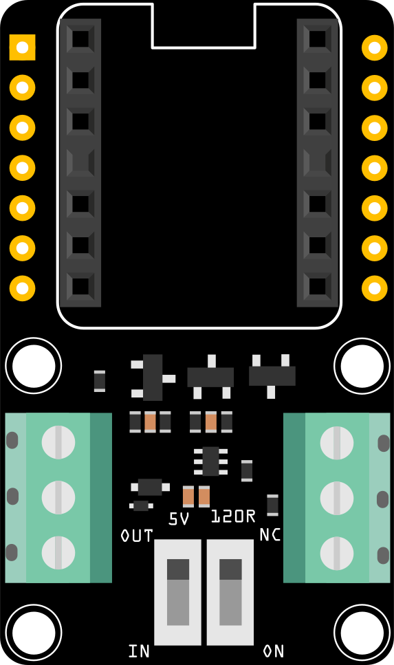
The RS-485 Breakout Board for XIAO is a compact and efficient module designed to enable RS-485 communication for the Seeed Studio XIAO microcontroller series. RS-485 is a robust communication standard that supports long-distance, high-speed, and reliable data transmission using differential signaling. This breakout board simplifies the integration of RS-485 communication into your projects, making it ideal for industrial automation, IoT applications, and other scenarios requiring noise-resistant data transfer over extended distances.

Explore Projects Built with RS-485 Breakout Board for XIAO

Use Cirkit Designer to design, explore, and prototype these projects online. Some projects support real-time simulation. Click "Open Project" to start designing instantly!
ESP8266 NodeMCU with LoRa and RS-485 Communication and Ethernet Connectivity
Image of Wiring Diagram LoRa: A project utilizing RS-485 Breakout Board for XIAO in a practical application
This circuit serves as a multi-protocol communication hub featuring two ESP8266 NodeMCUs for processing, each connected to a LoRa Ra-02 SX1278 for long-range wireless communication. One NodeMCU is also connected to an RS-485 module for serial communication and a W5500 Ethernet module for network connectivity, with MB102 modules supplying power.
Cirkit Designer LogoOpen Project in Cirkit Designer
ESP8266 NodeMCU with LoRa and RS-485 Communication Interface
Image of RS485 Serial USB: A project utilizing RS-485 Breakout Board for XIAO in a practical application
This circuit features two ESP8266 NodeMCU microcontrollers, each interfaced with a LoRa Ra-02 SX1278 module for long-range wireless communication, and an RS-485 module for wired serial communication. The ESP8266 microcontrollers are responsible for handling the communication protocols and data processing. Power is supplied to the microcontrollers via an MB102 Breadboard Power Supply Module, which provides both 3.3V and 5V outputs.
Cirkit Designer LogoOpen Project in Cirkit Designer
ESP32-Based Industrial Control System with RS485 Communication and I2C Interface
Image of DRIVER TESTER : A project utilizing RS-485 Breakout Board for XIAO in a practical application
This circuit integrates a microcontroller with a display, digital potentiometer, IO expander, and opto-isolator board for signal interfacing and isolation. It includes a UART to RS485 converter for serial communication and a power converter to step down voltage for the system. The circuit is designed for control and communication in an isolated and protected environment.
Cirkit Designer LogoOpen Project in Cirkit Designer
STM32 and Arduino UNO Based Dual RS485 Communication Interface
Image of STM to Arduino RS485: A project utilizing RS-485 Breakout Board for XIAO in a practical application
This circuit consists of two microcontrollers, an STM32F103C8T6 and an Arduino UNO, each interfaced with separate RS485 transceiver modules for serial communication. The STM32F103C8T6 controls the RE (Receiver Enable) and DE (Driver Enable) pins of one RS485 module to manage its operation, and communicates via the A9 and A10 pins for DI (Data Input) and RO (Receiver Output), respectively. The Arduino UNO is similarly connected to another RS485 module, with digital pins D2 and D3 interfacing with DI and RO, and D8 controlling both RE and DE. The RS485 modules are connected to each other through their A and B differential communication lines, enabling serial data exchange between the two microcontrollers over a robust and long-distance capable RS485 network.
Cirkit Designer LogoOpen Project in Cirkit Designer

Explore Projects Built with RS-485 Breakout Board for XIAO

Use Cirkit Designer to design, explore, and prototype these projects online. Some projects support real-time simulation. Click "Open Project" to start designing instantly!
Image of Wiring Diagram LoRa: A project utilizing RS-485 Breakout Board for XIAO in a practical application
ESP8266 NodeMCU with LoRa and RS-485 Communication and Ethernet Connectivity
This circuit serves as a multi-protocol communication hub featuring two ESP8266 NodeMCUs for processing, each connected to a LoRa Ra-02 SX1278 for long-range wireless communication. One NodeMCU is also connected to an RS-485 module for serial communication and a W5500 Ethernet module for network connectivity, with MB102 modules supplying power.
Cirkit Designer LogoOpen Project in Cirkit Designer
Image of RS485 Serial USB: A project utilizing RS-485 Breakout Board for XIAO in a practical application
ESP8266 NodeMCU with LoRa and RS-485 Communication Interface
This circuit features two ESP8266 NodeMCU microcontrollers, each interfaced with a LoRa Ra-02 SX1278 module for long-range wireless communication, and an RS-485 module for wired serial communication. The ESP8266 microcontrollers are responsible for handling the communication protocols and data processing. Power is supplied to the microcontrollers via an MB102 Breadboard Power Supply Module, which provides both 3.3V and 5V outputs.
Cirkit Designer LogoOpen Project in Cirkit Designer
Image of DRIVER TESTER : A project utilizing RS-485 Breakout Board for XIAO in a practical application
ESP32-Based Industrial Control System with RS485 Communication and I2C Interface
This circuit integrates a microcontroller with a display, digital potentiometer, IO expander, and opto-isolator board for signal interfacing and isolation. It includes a UART to RS485 converter for serial communication and a power converter to step down voltage for the system. The circuit is designed for control and communication in an isolated and protected environment.
Cirkit Designer LogoOpen Project in Cirkit Designer
Image of STM to Arduino RS485: A project utilizing RS-485 Breakout Board for XIAO in a practical application
STM32 and Arduino UNO Based Dual RS485 Communication Interface
This circuit consists of two microcontrollers, an STM32F103C8T6 and an Arduino UNO, each interfaced with separate RS485 transceiver modules for serial communication. The STM32F103C8T6 controls the RE (Receiver Enable) and DE (Driver Enable) pins of one RS485 module to manage its operation, and communicates via the A9 and A10 pins for DI (Data Input) and RO (Receiver Output), respectively. The Arduino UNO is similarly connected to another RS485 module, with digital pins D2 and D3 interfacing with DI and RO, and D8 controlling both RE and DE. The RS485 modules are connected to each other through their A and B differential communication lines, enabling serial data exchange between the two microcontrollers over a robust and long-distance capable RS485 network.
Cirkit Designer LogoOpen Project in Cirkit Designer

Common Applications and Use Cases

  • Industrial automation and control systems
  • IoT networks with long-distance communication
  • Building management systems (e.g., HVAC, lighting control)
  • Robotics and sensor networks
  • Data acquisition systems

Technical Specifications

The RS-485 Breakout Board for XIAO is designed to work seamlessly with the XIAO microcontroller series. Below are the key technical details:

General Specifications

Parameter Value
Communication Standard RS-485
Operating Voltage 3.3V / 5V (XIAO compatible)
Data Transmission Rate Up to 10 Mbps
Communication Distance Up to 1200 meters (4000 feet)
Connector Type Screw terminals for RS-485
Dimensions Compact, XIAO-compatible size

Pin Configuration and Descriptions

The breakout board connects directly to the XIAO microcontroller and provides screw terminals for RS-485 communication. Below is the pin configuration:

XIAO Pinout

Pin Name Description
VCC Power input (3.3V or 5V)
GND Ground
TX Transmit data (connected to DI pin)
RX Receive data (connected to RO pin)

RS-485 Screw Terminal Pinout

Terminal Name Description
A (D+) Non-inverting RS-485 signal (Data+)
B (D-) Inverting RS-485 signal (Data-)
GND Ground

Usage Instructions

How to Use the Component in a Circuit

  1. Power the Board: Connect the VCC and GND pins of the breakout board to the corresponding pins on the XIAO microcontroller.
  2. Connect RS-485 Terminals: Use the screw terminals to connect the A (D+), B (D-), and GND lines to your RS-485 network.
  3. Connect TX and RX: Link the TX and RX pins of the XIAO to the DI (Driver Input) and RO (Receiver Output) pins of the RS-485 transceiver on the breakout board.
  4. Termination Resistor: If the breakout board is at the end of the RS-485 bus, ensure a 120-ohm termination resistor is connected between A (D+) and B (D-).

Important Considerations and Best Practices

  • Voltage Compatibility: Ensure the XIAO microcontroller and the breakout board share the same operating voltage (3.3V or 5V).
  • Bus Topology: RS-485 requires a daisy-chain topology with termination resistors at both ends of the bus.
  • Signal Integrity: Use twisted-pair cables for the A (D+) and B (D-) lines to minimize noise and signal degradation.
  • Grounding: Ensure all devices on the RS-485 network share a common ground to avoid communication issues.

Example Code for Arduino UNO (with XIAO)

Below is an example of how to use the RS-485 Breakout Board for XIAO with the Arduino IDE. This code demonstrates basic RS-485 communication.

#include <SoftwareSerial.h>

// Define RS-485 pins
#define RS485_TX_PIN 1  // XIAO TX pin connected to DI
#define RS485_RX_PIN 0  // XIAO RX pin connected to RO

// Create a SoftwareSerial object for RS-485 communication
SoftwareSerial RS485Serial(RS485_RX_PIN, RS485_TX_PIN);

void setup() {
  // Initialize serial communication
  Serial.begin(9600);  // For debugging via USB
  RS485Serial.begin(9600);  // RS-485 communication baud rate

  Serial.println("RS-485 Communication Initialized");
}

void loop() {
  // Send data over RS-485
  RS485Serial.println("Hello, RS-485!");

  // Check for incoming data
  if (RS485Serial.available()) {
    String receivedData = RS485Serial.readString();
    Serial.print("Received: ");
    Serial.println(receivedData);
  }

  delay(1000);  // Wait 1 second before sending the next message
}

Troubleshooting and FAQs

Common Issues Users Might Face

  1. No Communication on RS-485 Bus:

    • Cause: Incorrect wiring or missing termination resistors.
    • Solution: Verify the connections and ensure 120-ohm resistors are installed at both ends of the RS-485 bus.
  2. Data Corruption or Noise:

    • Cause: Long cable runs or improper grounding.
    • Solution: Use twisted-pair cables and ensure all devices share a common ground.
  3. XIAO Not Responding:

    • Cause: Incorrect pin connections or mismatched baud rates.
    • Solution: Double-check the TX and RX connections and ensure the baud rate in the code matches the RS-485 network.

Solutions and Tips for Troubleshooting

  • Use a multimeter to check continuity and voltage levels on the RS-485 lines.
  • Test the breakout board with a shorter cable to rule out signal degradation over long distances.
  • If using multiple devices on the RS-485 bus, ensure each device has a unique address or identifier in your communication protocol.

By following this documentation, you can effectively integrate the RS-485 Breakout Board for XIAO into your projects and achieve reliable long-distance communication.