Cirkit Designer Logo
Cirkit Designer
Your all-in-one circuit design IDE
Home / 
Component Documentation

How to Use GPS NEO 6M : Examples, Pinouts, and Specs

Image of GPS NEO 6M
Cirkit Designer LogoDesign with GPS NEO 6M in Cirkit Designer

Introduction

The GPS NEO 6M module is a compact, high-performance GPS (Global Positioning System) receiver with an integrated NEO-6M GPS chip that provides accurate positioning and navigation information. This module is widely used in various applications such as vehicle tracking systems, asset tracking, personal navigation devices, and drones.

Explore Projects Built with GPS NEO 6M

Use Cirkit Designer to design, explore, and prototype these projects online. Some projects support real-time simulation. Click "Open Project" to start designing instantly!
ESP32-Based GPS Tracker with OLED Display and Telegram Integration
Image of Yoon: A project utilizing GPS NEO 6M  in a practical application
This circuit is a GPS-based tracking system that uses an ESP32 microcontroller to receive GPS data from a NEO 6M module and display the coordinates on a 1.3" OLED screen. It also features WiFi connectivity to send location updates to a remote server, potentially for applications such as asset tracking or navigation assistance.
Cirkit Designer LogoOpen Project in Cirkit Designer
ESP32-Based GPS Tracker with OLED Display and Firebase Integration
Image of ecs: A project utilizing GPS NEO 6M  in a practical application
This circuit is a GPS tracking system that uses an ESP32 microcontroller to read location data from a NEO-6M GPS module and display information on a 0.96" OLED screen. The system is powered by a 2000mAh battery with a lithium-ion charger, and it uploads the GPS data to Firebase via WiFi. Additional components include an MPU6050 accelerometer/gyroscope for motion sensing and a buzzer for alerts.
Cirkit Designer LogoOpen Project in Cirkit Designer
Arduino Mega 2560 GPS Data Logger with NEO 6M Module
Image of Dhanshri project: A project utilizing GPS NEO 6M  in a practical application
This circuit interfaces a GPS NEO 6M module with an Arduino Mega 2560 microcontroller. The Arduino reads data from the GPS module via serial communication and prints it to the Serial Monitor for further analysis or display.
Cirkit Designer LogoOpen Project in Cirkit Designer
Arduino UNO GPS Tracker with OLED Display
Image of Speedometer using ardunio uno: A project utilizing GPS NEO 6M  in a practical application
This circuit integrates an Arduino UNO with an OLED display and a GPS NEO 6M module. The Arduino UNO controls the OLED display via I2C communication and receives GPS data through serial communication, enabling the display of real-time location information.
Cirkit Designer LogoOpen Project in Cirkit Designer

Explore Projects Built with GPS NEO 6M

Use Cirkit Designer to design, explore, and prototype these projects online. Some projects support real-time simulation. Click "Open Project" to start designing instantly!
Image of Yoon: A project utilizing GPS NEO 6M  in a practical application
ESP32-Based GPS Tracker with OLED Display and Telegram Integration
This circuit is a GPS-based tracking system that uses an ESP32 microcontroller to receive GPS data from a NEO 6M module and display the coordinates on a 1.3" OLED screen. It also features WiFi connectivity to send location updates to a remote server, potentially for applications such as asset tracking or navigation assistance.
Cirkit Designer LogoOpen Project in Cirkit Designer
Image of ecs: A project utilizing GPS NEO 6M  in a practical application
ESP32-Based GPS Tracker with OLED Display and Firebase Integration
This circuit is a GPS tracking system that uses an ESP32 microcontroller to read location data from a NEO-6M GPS module and display information on a 0.96" OLED screen. The system is powered by a 2000mAh battery with a lithium-ion charger, and it uploads the GPS data to Firebase via WiFi. Additional components include an MPU6050 accelerometer/gyroscope for motion sensing and a buzzer for alerts.
Cirkit Designer LogoOpen Project in Cirkit Designer
Image of Dhanshri project: A project utilizing GPS NEO 6M  in a practical application
Arduino Mega 2560 GPS Data Logger with NEO 6M Module
This circuit interfaces a GPS NEO 6M module with an Arduino Mega 2560 microcontroller. The Arduino reads data from the GPS module via serial communication and prints it to the Serial Monitor for further analysis or display.
Cirkit Designer LogoOpen Project in Cirkit Designer
Image of Speedometer using ardunio uno: A project utilizing GPS NEO 6M  in a practical application
Arduino UNO GPS Tracker with OLED Display
This circuit integrates an Arduino UNO with an OLED display and a GPS NEO 6M module. The Arduino UNO controls the OLED display via I2C communication and receives GPS data through serial communication, enabling the display of real-time location information.
Cirkit Designer LogoOpen Project in Cirkit Designer

Common Applications and Use Cases

  • Vehicle navigation and tracking
  • Asset tracking
  • Personal navigation and fitness devices
  • Geocaching
  • UAVs and drones for geolocation

Technical Specifications

Key Technical Details

  • Receiver Type: 50 Channels, GPS L1 frequency, C/A Code
  • Position Accuracy: 2.5 meters CEP (Circular Error Probable)
  • Update Rate: Up to 5 Hz
  • Acquisition Times: Cold starts: 27s (typ.), Hot starts: 1s (typ.)
  • Sensitivity: Tracking & Navigation: -161 dBm
  • Operating Voltage: 3.3V to 5V DC
  • Power Consumption: 50mA (typical)
  • Communication Interface: UART TTL (Serial)
  • Operating Temperature: -40°C to 85°C

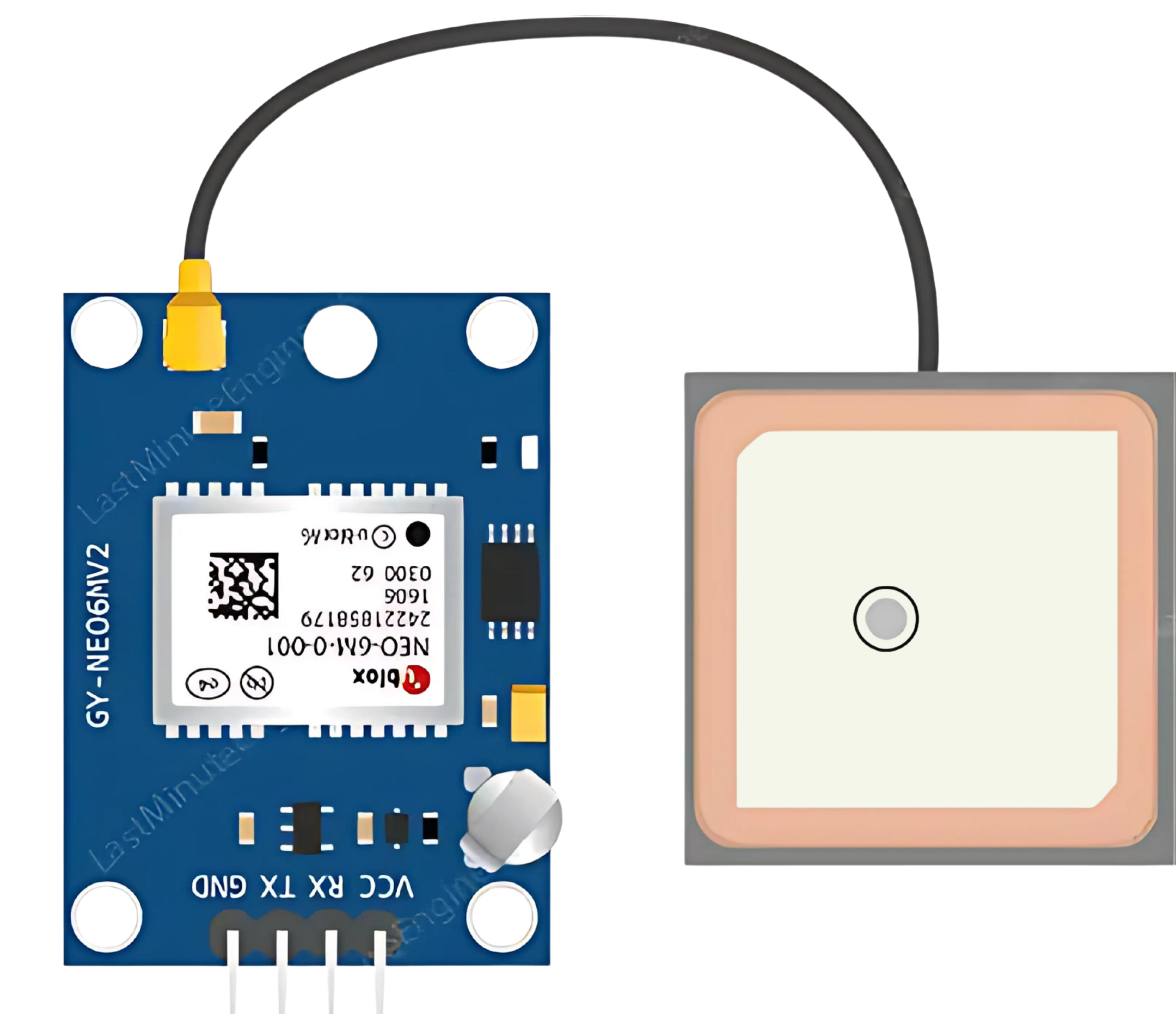
Pin Configuration and Descriptions

Pin Number Name Description
1 VCC Power supply (3.3V to 5V DC)
2 GND Ground connection
3 TX Transmit pin for UART communication
4 RX Receive pin for UART communication
5 PPS Pulse Per Second (optional, not always used)

Usage Instructions

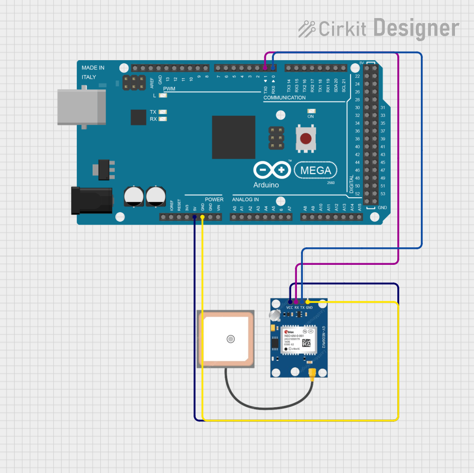
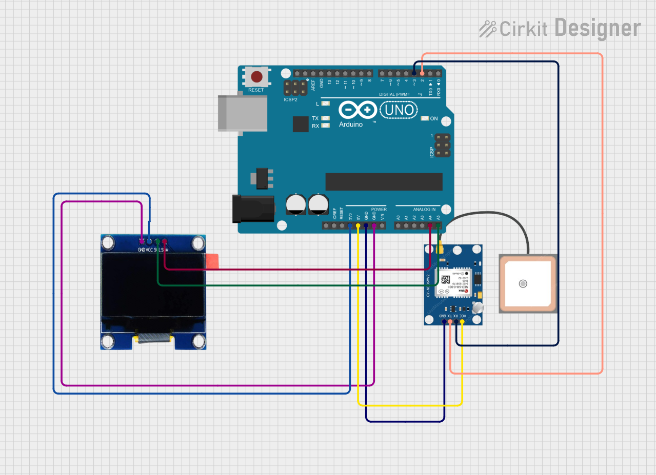
How to Use the Component in a Circuit

  1. Power Connection: Connect the VCC pin to a 3.3V or 5V power supply and the GND pin to the ground.
  2. Data Connection: Connect the TX pin of the GPS module to the RX pin of the microcontroller and the RX pin to the TX pin.
  3. Antenna: Ensure the GPS module's antenna has a clear view of the sky for optimal performance.

Important Considerations and Best Practices

  • Power Supply: Ensure that the power supply is stable and within the specified voltage range.
  • Serial Communication: Configure the microcontroller's UART interface to match the GPS module's default baud rate (usually 9600 bps).
  • Antenna Placement: Place the antenna away from large metal objects and electronic devices that may cause interference.
  • Warm-Up Time: Allow the module a few minutes to warm up and acquire satellites upon initial power-up.

Example Code for Arduino UNO

#include <SoftwareSerial.h>

// Create a SoftwareSerial port
SoftwareSerial gpsSerial(3, 4); // RX, TX

void setup() {
  // Start the serial communication
  Serial.begin(9600);
  gpsSerial.begin(9600);
  Serial.println("GPS NEO 6M test");
}

void loop() {
  // Check if data is available to read
  if (gpsSerial.available()) {
    char c = gpsSerial.read();
    Serial.write(c); // Print the GPS data to the Serial Monitor
  }
}

Troubleshooting and FAQs

Common Issues Users Might Face

  • No Data Output: Ensure the antenna has a clear view of the sky and the module has had sufficient time to acquire satellites.
  • Garbled Data: Check the baud rate settings and wiring connections between the GPS module and the microcontroller.
  • Inaccurate Position: Make sure the antenna is not obstructed and the module is stationary for initial position fixing.

Solutions and Tips for Troubleshooting

  • Power Cycle: If the module is not responding, try power cycling the module.
  • Check Connections: Verify all connections are secure and correct.
  • External Antenna: If the signal is weak, consider using an external antenna with a clear view of the sky.

FAQs

Q: How long does it take for the GPS NEO 6M to get a fix? A: It typically takes 27 seconds for a cold start and 1 second for a hot start.

Q: Can I use the GPS NEO 6M indoors? A: GPS signals are weak indoors. It's recommended to use the module outdoors or near a window.

Q: What is the default baud rate of the GPS NEO 6M? A: The default baud rate is usually 9600 bps.

Q: How can I change the update rate of the GPS module? A: The update rate can be changed using UBX protocol commands, which are beyond the scope of this basic documentation. Please refer to the module's datasheet for advanced configurations.