How to Use hall effect KY O24: Examples, Pinouts, and Specs
Introduction
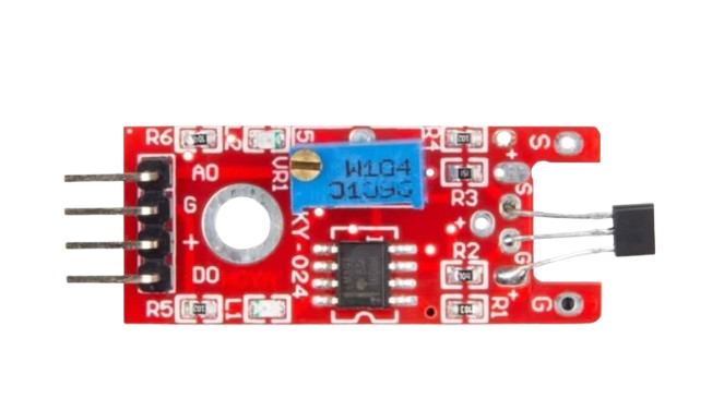
The Hall Effect KY-024 sensor is a magnetic field detection module that converts magnetic field variations into electrical signals. It is widely used in applications such as position sensing, proximity detection, speed measurement, and current sensing. The module combines a Hall effect sensor and a potentiometer for sensitivity adjustment, making it versatile and easy to integrate into various projects.
Common applications include:
- Detecting the presence or absence of a magnetic field
- Measuring rotational speed in motors
- Current sensing in power systems
- Position sensing in robotics and automation
Explore Projects Built with hall effect KY O24


Explore Projects Built with hall effect KY O24
Technical Specifications
The KY-024 module is designed for ease of use and compatibility with microcontrollers like Arduino. Below are its key technical details:
Key Specifications
| Parameter | Value |
|---|---|
| Operating Voltage | 3.3V - 5V |
| Output Type | Digital and Analog |
| Digital Output Voltage | 0V (Low) or Vcc (High) |
| Analog Output Voltage | 0V to Vcc |
| Sensitivity Adjustment | Via onboard potentiometer |
| Dimensions | 32mm x 14mm x 7mm |
Pin Configuration
The KY-024 module has three pins for connection. The table below describes each pin:
| Pin Name | Description |
|---|---|
| VCC | Power supply input (3.3V - 5V) |
| GND | Ground |
| D0 | Digital output (High/Low based on threshold) |
| A0 | Analog output (proportional to magnetic field strength) |
Usage Instructions
The KY-024 Hall Effect sensor is straightforward to use in a circuit. Follow the steps below to integrate it into your project:
Connecting the KY-024 to an Arduino UNO
- Connect the VCC pin of the KY-024 to the 5V pin on the Arduino.
- Connect the GND pin of the KY-024 to the GND pin on the Arduino.
- Connect the D0 pin to a digital input pin on the Arduino (e.g., pin 2).
- Optionally, connect the A0 pin to an analog input pin on the Arduino (e.g., A0) for more precise measurements.
Sample Arduino Code
The following code demonstrates how to use the KY-024 with an Arduino UNO to read both digital and analog outputs:
// Define pin connections
const int digitalPin = 2; // KY-024 D0 connected to digital pin 2
const int analogPin = A0; // KY-024 A0 connected to analog pin A0

void setup() {
  pinMode(digitalPin, INPUT); // Set digital pin as input
  Serial.begin(9600);         // Initialize serial communication
}

void loop() {
  // Read digital output (High/Low)
  int digitalValue = digitalRead(digitalPin);

  // Read analog output (0-1023)
  int analogValue = analogRead(analogPin);

  // Print values to the Serial Monitor
  Serial.print("Digital Output: ");
  Serial.print(digitalValue);
  Serial.print(" | Analog Output: ");
  Serial.println(analogValue);

  delay(500); // Delay for readability
}
Important Considerations
- Sensitivity Adjustment: Use the onboard potentiometer to adjust the sensitivity of the sensor. Turning the potentiometer clockwise increases sensitivity, while turning it counterclockwise decreases it.
- Magnetic Field Polarity: The sensor is sensitive to the polarity of the magnetic field. Ensure the correct orientation of the magnet for accurate readings.
- Power Supply: Ensure a stable power supply within the operating voltage range (3.3V - 5V) to avoid erratic behavior.
Troubleshooting and FAQs
Common Issues and Solutions
No Output from the Sensor
- Ensure the sensor is properly powered (check VCC and GND connections).
- Verify that the magnet is within the detection range of the sensor.
- Adjust the potentiometer to increase sensitivity.
Inconsistent Readings
- Check for electrical noise or interference in the circuit.
- Ensure a stable power supply to the sensor.
- Verify that the magnet is not moving too quickly for the sensor to detect.
Analog Output Always Reads Zero
- Confirm that the A0 pin is correctly connected to an analog input pin on the microcontroller.
- Ensure the magnet is close enough to the sensor to generate a measurable signal.
FAQs
Q: Can the KY-024 detect non-magnetic materials?
A: No, the KY-024 is specifically designed to detect magnetic fields and will not respond to non-magnetic materials.
Q: How far can the sensor detect a magnetic field?
A: The detection range depends on the strength of the magnetic field and the sensitivity setting. Typically, it can detect magnets within a few centimeters.
Q: Can I use the KY-024 with a 3.3V microcontroller?
A: Yes, the KY-024 operates within a voltage range of 3.3V to 5V, making it compatible with 3.3V microcontrollers like the ESP32 or Raspberry Pi Pico.
By following this documentation, you can effectively integrate the KY-024 Hall Effect sensor into your projects for reliable magnetic field detection.