
How to Use HN21RN-54HT510W: Examples, Pinouts, and Specs
 Design with HN21RN-54HT510W in Cirkit Designer
Introduction
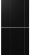
The HN21RN-54HT510W is a high-performance resistor network manufactured by Solar Hanersun. It is designed for precision applications, offering a resistance value of 510 ohms and a power rating of 54 watts. This component is ideal for use in electronic circuits requiring stable and reliable resistance under high-power conditions. Its robust design ensures consistent performance in demanding environments.
Explore Projects Built with HN21RN-54HT510W
 Open Project in Cirkit Designer
 Open Project in Cirkit Designer
 Open Project in Cirkit Designer
 Open Project in Cirkit Designer
Explore Projects Built with HN21RN-54HT510W
Open Project in Cirkit DesignerOpen Project in Cirkit DesignerOpen Project in Cirkit DesignerOpen Project in Cirkit DesignerCommon Applications and Use Cases
- Power supply circuits
- Voltage divider networks
- Signal conditioning and filtering
- Precision measurement systems
- Industrial control systems
Technical Specifications
The following table outlines the key technical details of the HN21RN-54HT510W resistor network:
| Parameter | Value |
|---|---|
| Manufacturer | Solar Hanersun |
| Part ID | Solar Hanersun 510WP FULL BLACK BIFACIAL 108 CELULAS N TYPE MC4 |
| Resistance Value | 510 ohms |
| Power Rating | 54 watts |
| Tolerance | ±1% |
| Temperature Coefficient | ±50 ppm/°C |
| Operating Temperature | -40°C to +125°C |
| Package Type | Through-hole |
| Number of Pins | 4 |
Pin Configuration and Descriptions
The HN21RN-54HT510W features a 4-pin configuration. The pinout is described in the table below:
| Pin Number | Pin Name | Description |
|---|---|---|
| 1 | Input A | Connects to the input voltage or signal source. |
| 2 | Output A | Provides the output voltage or signal for branch A. |
| 3 | Input B | Connects to the input voltage or signal source. |
| 4 | Output B | Provides the output voltage or signal for branch B. |
Usage Instructions
How to Use the Component in a Circuit
- Determine the Application: Identify the circuit requirements, such as the desired resistance and power dissipation.
- Connect the Pins:
- Connect Input A (Pin 1) and Input B (Pin 3) to the voltage or signal sources.
- Connect Output A (Pin 2) and Output B (Pin 4) to the respective load or circuit branches.
- Ensure Proper Heat Dissipation: Since the component has a power rating of 54 watts, ensure adequate heat sinking or ventilation to prevent overheating.
- Verify Connections: Double-check all connections to avoid short circuits or incorrect wiring.
Important Considerations and Best Practices
- Power Handling: Do not exceed the 54-watt power rating to avoid damaging the resistor network.
- Tolerance: Take the ±1% tolerance into account when designing precision circuits.
- Temperature Management: Operate the component within the specified temperature range (-40°C to +125°C) to ensure reliability.
- Mounting: Use appropriate through-hole mounting techniques to secure the component firmly on the PCB.
Example: Using with an Arduino UNO
The HN21RN-54HT510W can be used in conjunction with an Arduino UNO for applications such as voltage division or signal conditioning. Below is an example of a simple voltage divider circuit:
Circuit Description
- The resistor network is used to divide a 5V input signal into a lower voltage suitable for an analog input pin on the Arduino.
Arduino Code
// Example code for reading a voltage divided by the HN21RN-54HT510W resistor network
// Ensure the resistor network is connected as a voltage divider to the Arduino analog pin A0.

const int analogPin = A0; // Analog pin connected to the voltage divider output
float voltage = 0.0;      // Variable to store the measured voltage

void setup() {
  Serial.begin(9600); // Initialize serial communication at 9600 baud
}

void loop() {
  int sensorValue = analogRead(analogPin); // Read the analog input
  voltage = sensorValue * (5.0 / 1023.0);  // Convert the reading to voltage
  Serial.print("Measured Voltage: ");
  Serial.print(voltage);
  Serial.println(" V");
  delay(1000); // Wait for 1 second before the next reading
}
Troubleshooting and FAQs
Common Issues Users Might Face
Overheating:
- Cause: Exceeding the power rating of 54 watts.
- Solution: Use a heat sink or ensure proper ventilation to dissipate heat effectively.
Incorrect Resistance Value:
- Cause: Manufacturing tolerance or incorrect connections.
- Solution: Verify the resistance value using a multimeter and ensure proper wiring.
Signal Distortion:
- Cause: Operating outside the specified temperature range or using the component in high-frequency circuits.
- Solution: Ensure the operating conditions are within the specified range and consider using additional filtering components if necessary.
FAQs
Q1: Can the HN21RN-54HT510W be used in high-frequency circuits?
A1: While the component is primarily designed for precision and power applications, it may not be suitable for high-frequency circuits due to potential parasitic inductance. Consider using specialized components for such applications.
Q2: How do I calculate the power dissipation in the resistor network?
A2: Use the formula ( P = I^2 \times R ), where ( P ) is the power, ( I ) is the current, and ( R ) is the resistance. Ensure the calculated power does not exceed 54 watts.
Q3: What is the recommended mounting method for this component?
A3: The HN21RN-54HT510W is a through-hole component. Use standard soldering techniques to mount it securely on the PCB, ensuring proper alignment and heat dissipation.
This concludes the documentation for the HN21RN-54HT510W resistor network. For further assistance, refer to the manufacturer's datasheet or contact technical support.