How to Use ESP32-38 PINS: Examples, Pinouts, and Specs
Introduction
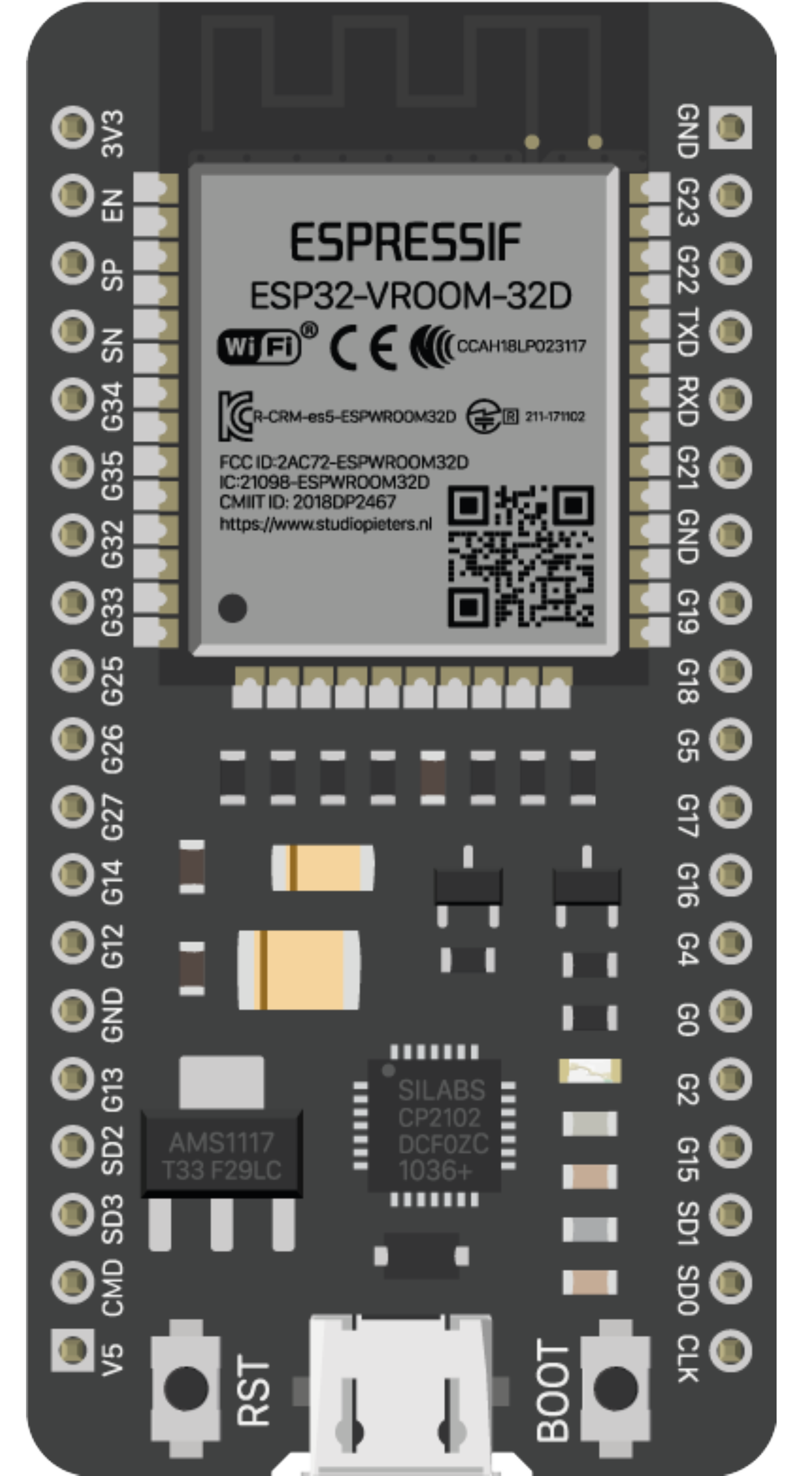
The ESP32-38 PINS, manufactured by Espressif Systems (Part ID: ESP32-WROOM-32), refers to the 38 GPIO (General Purpose Input/Output) pins available on the ESP32 microcontroller. The ESP32 is a powerful, low-cost microcontroller with built-in Wi-Fi and Bluetooth capabilities, making it ideal for IoT (Internet of Things) applications. These GPIO pins are highly versatile and can be configured for various functions, including digital input/output, analog input, PWM output, I2C, SPI, UART, and more.
Explore Projects Built with ESP32-38 PINS


Explore Projects Built with ESP32-38 PINS
Common Applications and Use Cases
- IoT devices and smart home automation
- Sensor interfacing and data acquisition
- Robotics and motor control
- Wireless communication (Wi-Fi and Bluetooth)
- Wearable devices
- Prototyping and development of embedded systems
Technical Specifications
The ESP32-38 PINS microcontroller offers a wide range of features and capabilities. Below are the key technical specifications and pin configuration details:
Key Technical Details
| Parameter | Specification |
|---|---|
| Microcontroller | ESP32-WROOM-32 |
| GPIO Pins | 38 |
| Operating Voltage | 3.3V |
| Input Voltage Range | 2.2V - 3.6V |
| Digital I/O Pins | 34 |
| Analog Input Pins (ADC) | 18 (12-bit resolution) |
| Analog Output Pins (DAC) | 2 (8-bit resolution) |
| PWM Channels | 16 |
| Communication Interfaces | UART, SPI, I2C, I2S, CAN |
| Wi-Fi Standard | 802.11 b/g/n |
| Bluetooth Standard | Bluetooth v4.2 + BLE |
| Flash Memory | 4MB |
| Clock Speed | Up to 240 MHz |
| Power Consumption | Ultra-low power (varies by mode) |
Pin Configuration and Descriptions
The ESP32-38 PINS has 38 GPIO pins, each with specific functions. Below is a table summarizing the pin configuration:
| Pin Number | Pin Name | Functionality |
|---|---|---|
| 1 | EN | Enable pin (active high, used to reset the chip) |
| 2 | IO0 | GPIO0, supports ADC, UART, PWM |
| 3 | IO1 | GPIO1, supports ADC, UART, PWM |
| 4 | IO2 | GPIO2, supports ADC, UART, PWM |
| 5 | IO3 | GPIO3, supports ADC, UART, PWM |
| ... | ... | ... (Refer to the ESP32 datasheet for the full pinout) |
| 37 | IO36 | GPIO36, ADC input only |
| 38 | IO39 | GPIO39, ADC input only |
Note: Some GPIO pins have specific restrictions or are used internally by the ESP32. Refer to the official datasheet for detailed pin functionality.
Usage Instructions
The ESP32-38 PINS can be used in a variety of circuits and applications. Below are the steps and best practices for using the component effectively:
How to Use the Component in a Circuit
- Powering the ESP32: Connect the 3.3V pin to a regulated 3.3V power source. Ensure the ground (GND) is connected to the circuit's ground.
- Configuring GPIO Pins: Use the ESP32's GPIO pins for digital input/output, analog input, or other functions. For example:
- Digital Input: Connect a button or switch to a GPIO pin.
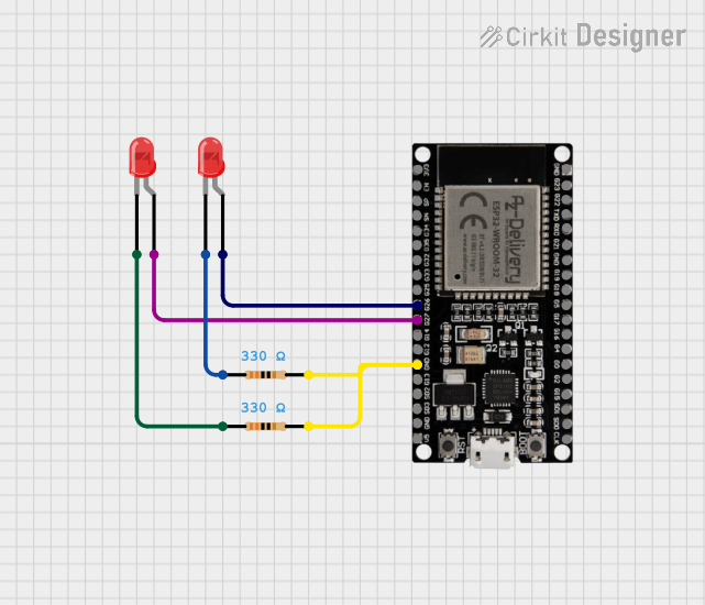
- Digital Output: Connect an LED with a current-limiting resistor to a GPIO pin.
- Analog Input: Connect a sensor output to an ADC-capable GPIO pin.
- Programming the ESP32: Use the Arduino IDE or ESP-IDF (Espressif IoT Development Framework) to write and upload code to the ESP32.
Important Considerations and Best Practices
- Voltage Levels: The ESP32 operates at 3.3V. Avoid applying 5V directly to GPIO pins to prevent damage.
- Pin Restrictions: Some GPIO pins are used internally (e.g., GPIO6-GPIO11 for flash memory) and should not be used for general I/O.
- Pull-up/Pull-down Resistors: Use appropriate pull-up or pull-down resistors for input pins to ensure stable operation.
- Power Supply: Use a stable power supply to avoid unexpected resets or malfunctions.
Example Code for Arduino UNO
Below is an example of how to blink an LED connected to GPIO2 on the ESP32 using the Arduino IDE:
// Define the GPIO pin for the LED
const int ledPin = 2; // GPIO2 is commonly used for onboard LEDs

void setup() {
  pinMode(ledPin, OUTPUT); // Set GPIO2 as an output pin
}

void loop() {
  digitalWrite(ledPin, HIGH); // Turn the LED on
  delay(1000);                // Wait for 1 second
  digitalWrite(ledPin, LOW);  // Turn the LED off
  delay(1000);                // Wait for 1 second
}
Note: Ensure the ESP32 is selected as the board in the Arduino IDE and the correct COM port is chosen before uploading the code.
Troubleshooting and FAQs
Common Issues Users Might Face
ESP32 Not Responding or Booting:
- Cause: Incorrect power supply or wiring.
- Solution: Ensure the ESP32 is powered with a stable 3.3V supply and all connections are secure.
GPIO Pin Not Working:
- Cause: Pin might be reserved for internal use or incorrectly configured.
- Solution: Check the pin's functionality in the datasheet and ensure it is not being used for another purpose.
Wi-Fi Connection Issues:
- Cause: Incorrect SSID/password or weak signal strength.
- Solution: Verify the Wi-Fi credentials and ensure the ESP32 is within range of the router.
Code Upload Fails:
- Cause: Incorrect board or COM port selected in the Arduino IDE.
- Solution: Select "ESP32 Dev Module" as the board and the correct COM port.
Solutions and Tips for Troubleshooting
- Use a multimeter to check voltage levels and continuity in the circuit.
- Refer to the ESP32 datasheet for detailed pin descriptions and electrical characteristics.
- Use serial debugging to identify issues in your code or hardware setup.
By following this documentation, users can effectively utilize the ESP32-38 PINS for a wide range of applications and troubleshoot common issues with ease.