How to Use piezo: Examples, Pinouts, and Specs
Introduction
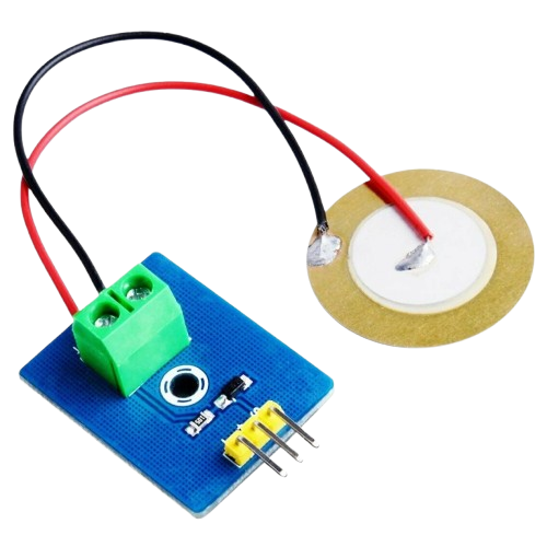
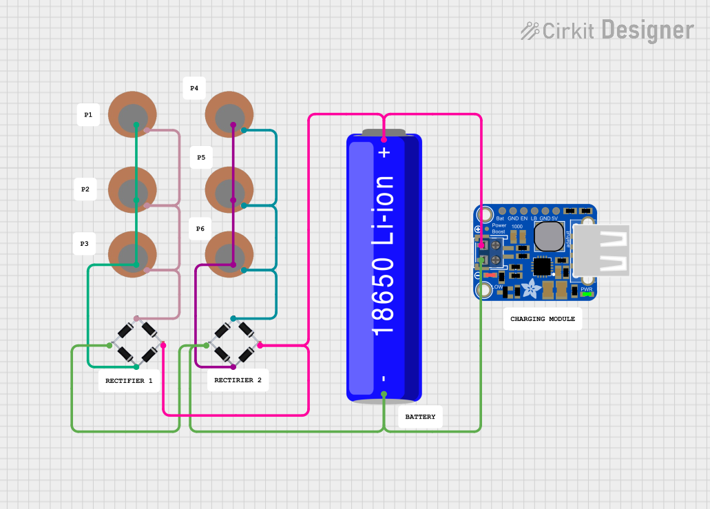
The Piezo by Candra is a piezoelectric component designed to generate an electric charge when subjected to mechanical stress. This versatile component is widely used in applications such as sound generation (e.g., buzzers), vibration sensors, and actuators. Its ability to convert mechanical energy into electrical energy (and vice versa) makes it an essential component in various electronic systems.
Explore Projects Built with piezo
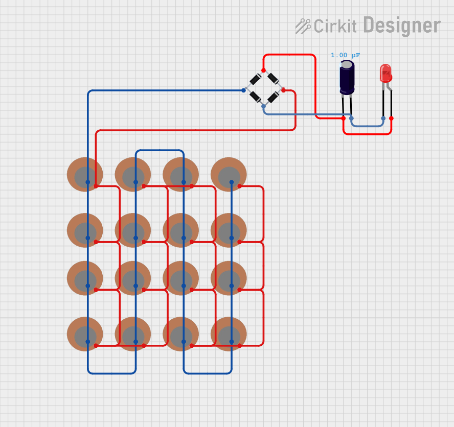
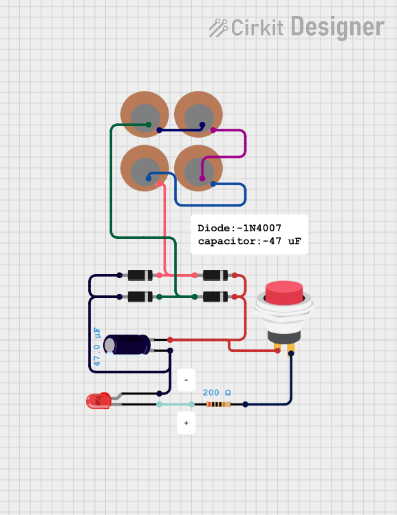
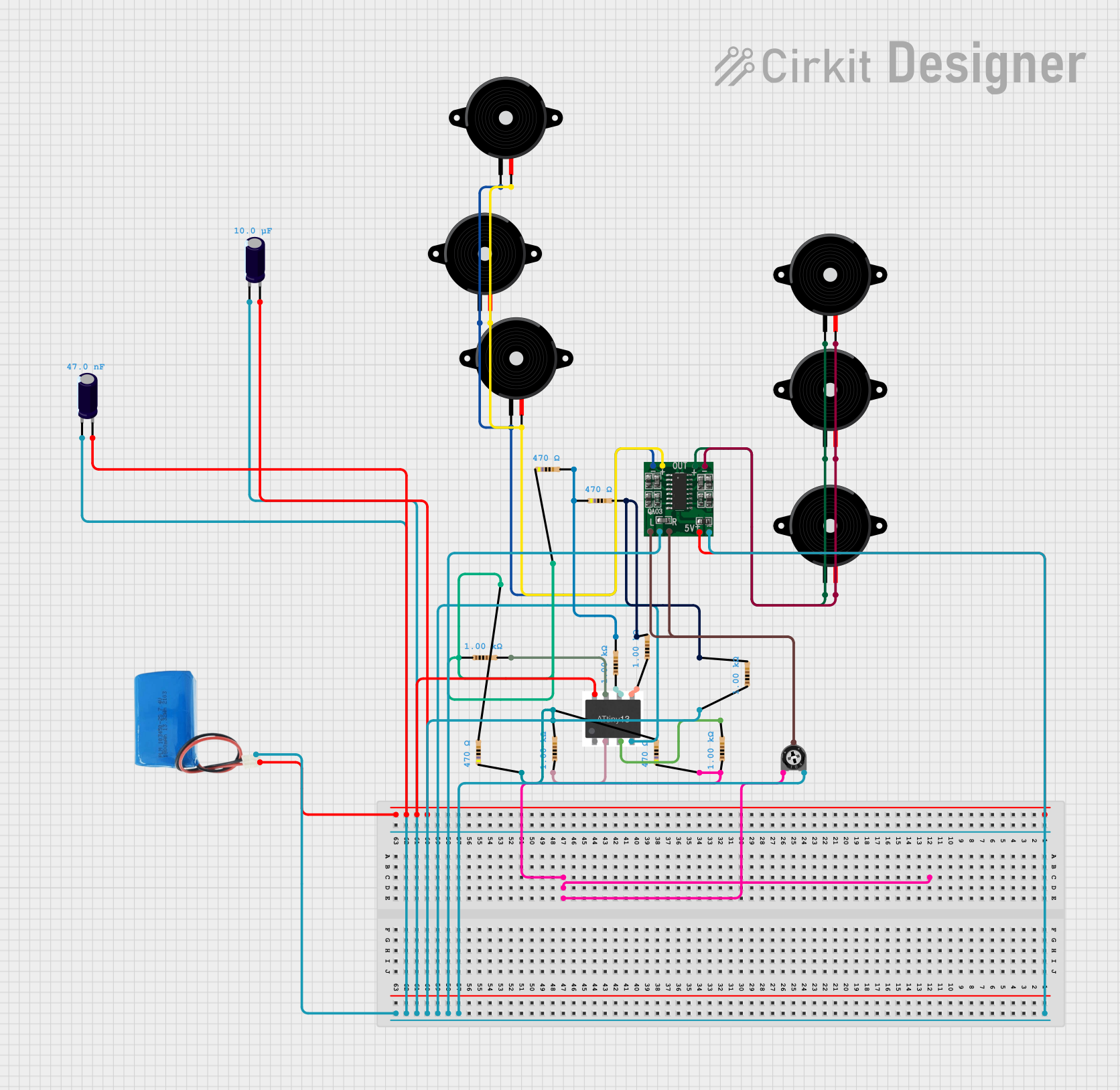
Explore Projects Built with piezo
Common Applications:
- Sound generation: Used in buzzers, alarms, and notification systems.
- Sensors: Detects vibrations, pressure, or impact in devices like accelerometers.
- Actuators: Converts electrical signals into mechanical motion in precision devices.
- Energy harvesting: Converts mechanical energy into electrical energy for low-power devices.
Technical Specifications
Below are the key technical details for the Candra Piezo:
| Parameter | Value |
|---|---|
| Operating Voltage | 3V to 12V |
| Resonant Frequency | 2 kHz to 4 kHz (varies by model) |
| Current Consumption | < 20 mA |
| Output Sound Pressure | 85 dB @ 10 cm (typical) |
| Operating Temperature | -20°C to +70°C |
| Dimensions | 20 mm diameter, 5 mm thickness |
Pin Configuration and Descriptions
The Candra Piezo typically has two pins:
| Pin | Name | Description |
|---|---|---|
| 1 | Positive (+) | Connect to the positive terminal of the power supply or signal source. |
| 2 | Negative (-) | Connect to the ground (GND) or negative terminal of the power supply. |
Note: Ensure correct polarity when connecting the piezo to avoid damage or improper operation.
Usage Instructions
How to Use the Piezo in a Circuit
Basic Sound Generation:
- Connect the positive pin of the piezo to a signal source (e.g., microcontroller pin or oscillator circuit).
- Connect the negative pin to the ground (GND).
- Use a current-limiting resistor (e.g., 1 kΩ) in series with the piezo to protect the circuit.
Driving with a Microcontroller (e.g., Arduino UNO):
- The piezo can be directly connected to a digital output pin of the Arduino.
- Use the
tone()function in Arduino to generate sound at specific frequencies.
Example Arduino Code
// Example: Generate a 1 kHz tone on a piezo connected to pin 8
const int piezoPin = 8; // Pin connected to the piezo

void setup() {
  // No setup required for tone generation
}

void loop() {
  tone(piezoPin, 1000); // Generate a 1 kHz tone
  delay(1000);          // Play the tone for 1 second
  noTone(piezoPin);     // Stop the tone
  delay(1000);          // Wait for 1 second before repeating
}
Important Considerations and Best Practices
- Polarity: Always connect the positive and negative pins correctly.
- Voltage Limits: Do not exceed the maximum operating voltage (12V) to avoid damaging the piezo.
- Frequency Range: Operate the piezo within its resonant frequency range (2 kHz to 4 kHz) for optimal performance.
- Mounting: Ensure the piezo is securely mounted to avoid mechanical vibrations affecting performance.
Troubleshooting and FAQs
Common Issues and Solutions
No Sound Output:
- Cause: Incorrect wiring or insufficient voltage.
- Solution: Verify the connections and ensure the voltage is within the operating range.
Distorted Sound:
- Cause: Operating outside the resonant frequency range.
- Solution: Adjust the frequency of the signal source to match the piezo's resonant frequency.
Overheating:
- Cause: Excessive current or prolonged operation at high voltage.
- Solution: Use a current-limiting resistor and ensure the voltage does not exceed 12V.
Intermittent Operation:
- Cause: Loose connections or mechanical stress on the piezo.
- Solution: Check and secure all connections. Avoid excessive mechanical stress.
FAQs
Q1: Can the piezo be used to detect vibrations?
A1: Yes, the piezo can act as a vibration sensor by generating a voltage in response to mechanical stress. Connect it to an analog input pin of a microcontroller to measure the voltage.
Q2: Can I use the piezo with a 5V power supply?
A2: Yes, the piezo operates effectively at 5V. Ensure the signal source provides sufficient current.
Q3: How do I increase the sound volume?
A3: Use a higher voltage within the operating range (e.g., 9V or 12V). Alternatively, use an amplifier circuit to drive the piezo.
Q4: Is the piezo waterproof?
A4: The standard Candra Piezo is not waterproof. For outdoor or wet environments, use a waterproof enclosure or a specialized waterproof piezo.
By following this documentation, you can effectively integrate the Candra Piezo into your projects for sound generation, sensing, or actuation.