How to Use XL47015 DC- DC STEP DOWN CONVERTER MODULE: Examples, Pinouts, and Specs
Introduction
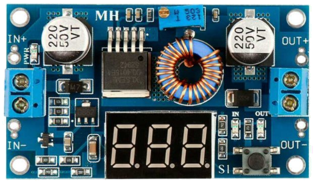
The XL4701-5 DC-DC Step Down Converter Module is a compact and efficient voltage regulator designed to convert a higher DC input voltage to a stable, lower DC output voltage. This module is based on the XL4701-5 chip, which ensures high efficiency and reliable performance. It is widely used in applications requiring stable power delivery, such as powering microcontrollers, sensors, and other electronic devices.
Explore Projects Built with XL47015 DC- DC STEP DOWN CONVERTER MODULE


Explore Projects Built with XL47015 DC- DC STEP DOWN CONVERTER MODULE
Common Applications and Use Cases
- Powering microcontrollers like Arduino, Raspberry Pi, and ESP32.
- Voltage regulation for battery-powered devices.
- Supplying power to sensors, motors, and other peripherals.
- DIY electronics projects requiring efficient voltage conversion.
Technical Specifications
The following table outlines the key technical details of the XL4701-5 DC-DC Step Down Converter Module:
| Parameter | Specification |
|---|---|
| Input Voltage Range | 4.5V to 40V |
| Output Voltage Range | 1.25V to 37V (adjustable) |
| Output Current | Up to 5A |
| Efficiency | Up to 92% |
| Switching Frequency | 300 kHz |
| Operating Temperature | -40°C to +85°C |
| Dimensions | 43mm x 21mm x 14mm |
Pin Configuration and Descriptions
The XL4701-5 module typically has the following pinout:
| Pin Name | Description |
|---|---|
| VIN | Input voltage (connect to DC power source) |
| GND | Ground (common ground for input and output) |
| VOUT | Regulated output voltage |
| ADJ | Voltage adjustment pin (via potentiometer) |
Usage Instructions
How to Use the XL4701-5 in a Circuit
Connect the Input Voltage (VIN):
- Connect the positive terminal of your DC power source to the
VINpin. - Connect the negative terminal of your power source to the
GNDpin.
- Connect the positive terminal of your DC power source to the
Adjust the Output Voltage (Optional):
- Use the onboard potentiometer to adjust the output voltage.
- Turn the potentiometer clockwise to increase the output voltage or counterclockwise to decrease it.
- Use a multimeter to measure the output voltage at the
VOUTpin while adjusting.
Connect the Load:
- Connect the positive terminal of your load to the
VOUTpin. - Connect the negative terminal of your load to the
GNDpin.
- Connect the positive terminal of your load to the
Power On:
- Once all connections are secure, power on the module by supplying voltage to the
VINpin. - Ensure the input voltage is within the specified range (4.5V to 40V).
- Once all connections are secure, power on the module by supplying voltage to the
Important Considerations and Best Practices
- Heat Dissipation: For high current loads, ensure proper heat dissipation by attaching a heatsink to the module if necessary.
- Input Voltage: Always ensure the input voltage is higher than the desired output voltage.
- Current Limit: Do not exceed the maximum output current of 5A to avoid damaging the module.
- Polarity: Double-check the polarity of your connections to prevent short circuits or damage.
- Filtering Capacitors: For sensitive applications, consider adding external capacitors to reduce noise and ripple.
Example: Using XL4701-5 with Arduino UNO
The XL4701-5 can be used to power an Arduino UNO by stepping down a 12V DC input to 5V. Below is an example circuit and Arduino code:
Circuit Connections
- Connect a 12V DC power source to the
VINandGNDpins of the XL4701-5 module. - Adjust the output voltage to 5V using the potentiometer.
- Connect the
VOUTpin to the Arduino UNO's5Vpin. - Connect the
GNDpin of the module to the Arduino UNO'sGNDpin.
Arduino Code Example
// Example code to blink an LED connected to pin 13 of Arduino UNO
// Ensure the XL4701-5 module is providing a stable 5V to the Arduino

void setup() {
  pinMode(13, OUTPUT); // Set pin 13 as an output
}

void loop() {
  digitalWrite(13, HIGH); // Turn the LED on
  delay(1000);            // Wait for 1 second
  digitalWrite(13, LOW);  // Turn the LED off
  delay(1000);            // Wait for 1 second
}
Troubleshooting and FAQs
Common Issues and Solutions
No Output Voltage:
- Cause: Incorrect wiring or insufficient input voltage.
- Solution: Double-check all connections and ensure the input voltage is within the specified range.
Output Voltage Not Adjustable:
- Cause: Faulty potentiometer or incorrect adjustment.
- Solution: Verify the potentiometer is functioning correctly and adjust it slowly while monitoring the output voltage.
Overheating:
- Cause: Excessive current draw or poor heat dissipation.
- Solution: Reduce the load current or attach a heatsink to the module.
High Output Ripple:
- Cause: Insufficient filtering or noisy input power.
- Solution: Add external capacitors (e.g., 100µF electrolytic and 0.1µF ceramic) to the input and output.
FAQs
Q: Can the XL4701-5 module be used with a 3.7V lithium-ion battery?
A: No, the input voltage must be at least 4.5V. A single 3.7V battery is insufficient.
Q: Is the module protected against reverse polarity?
A: No, the module does not have built-in reverse polarity protection. Always ensure correct polarity.
Q: Can I use this module to power a Raspberry Pi?
A: Yes, but ensure the output voltage is set to 5V and the current requirement of the Raspberry Pi is within the module's 5A limit.
Q: How do I reduce noise in the output voltage?
A: Add external filtering capacitors and ensure the input power source is stable and clean.
This concludes the documentation for the XL4701-5 DC-DC Step Down Converter Module.