How to Use 2 channel CAN FD for Raspberry Pi: Examples, Pinouts, and Specs
Introduction
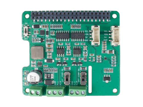
The 2-Channel CAN FD Shield for Raspberry Pi is an expansion board that enables two-channel Controller Area Network with Flexible Data-Rate (CAN FD) communication for Raspberry Pi computers. This shield allows Raspberry Pi users to communicate with CAN FD networks, which are commonly used in automotive and industrial applications due to their high reliability and speed. The shield is particularly useful for developing telematics applications, automotive diagnostics, industrial automation systems, and for integrating Raspberry Pi into existing CAN FD networks.
Explore Projects Built with 2 channel CAN FD for Raspberry Pi
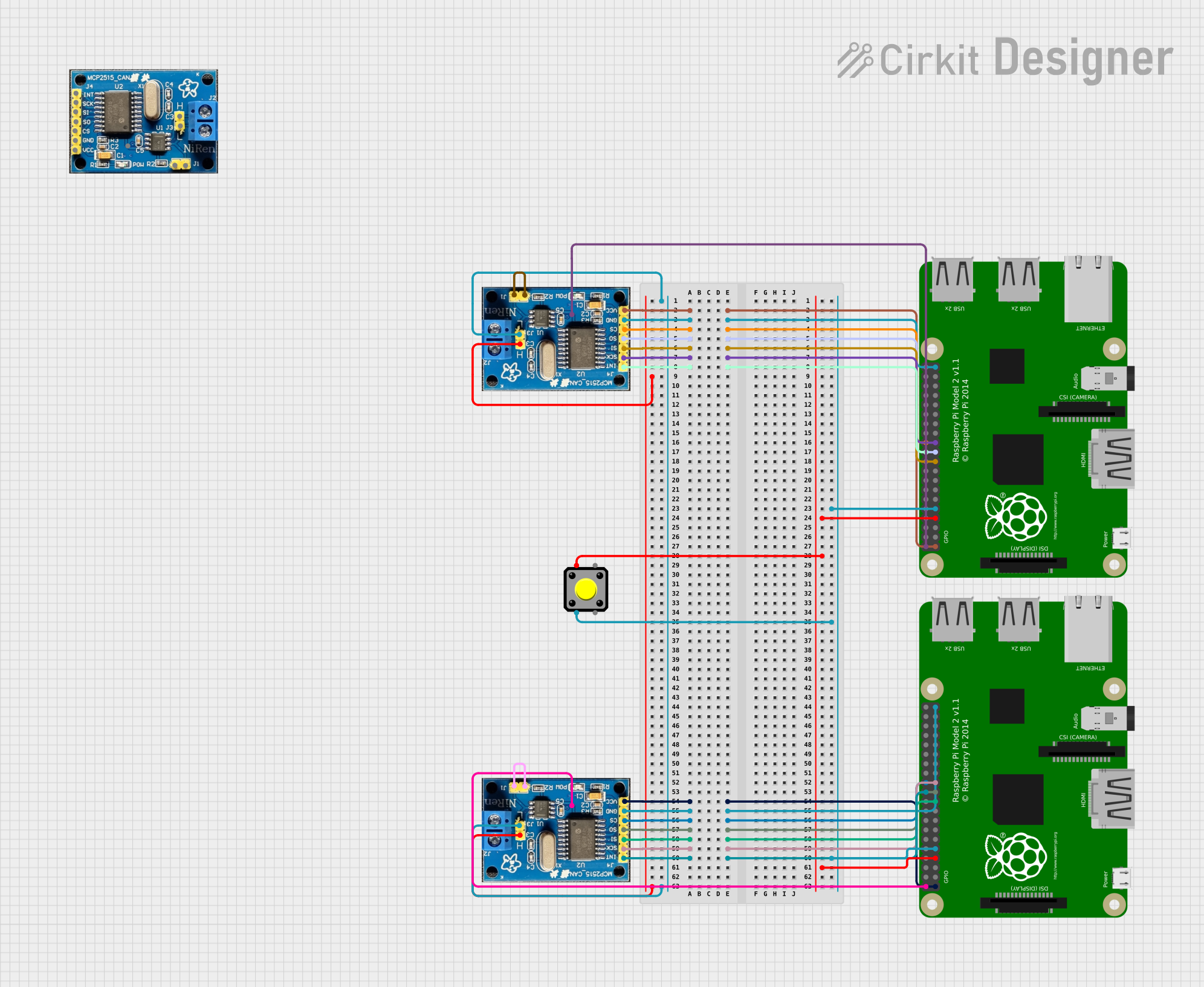
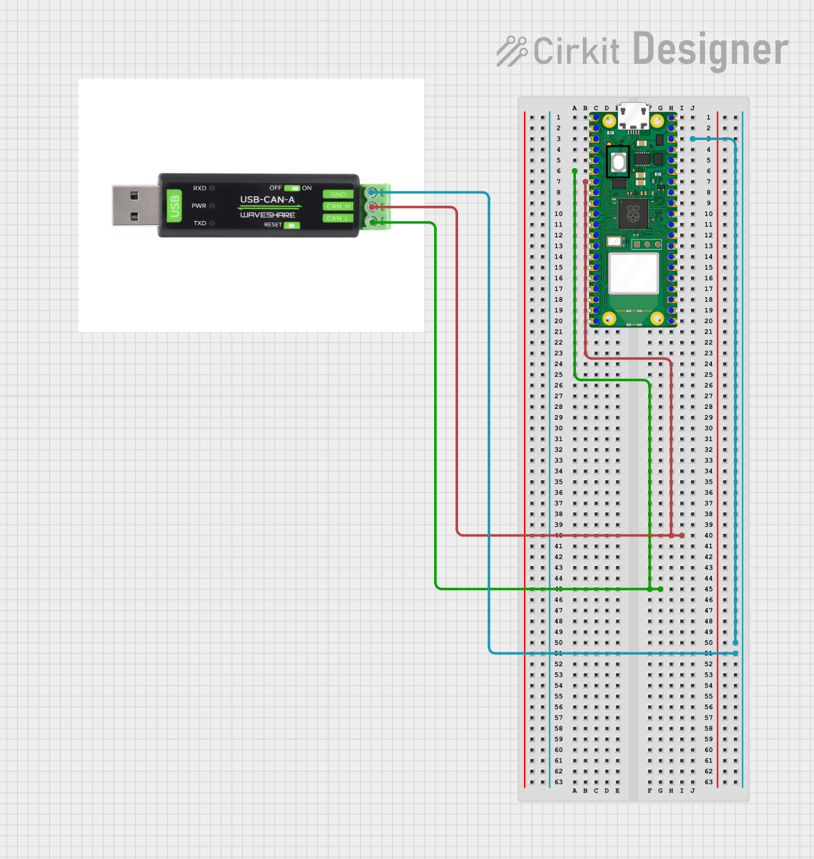
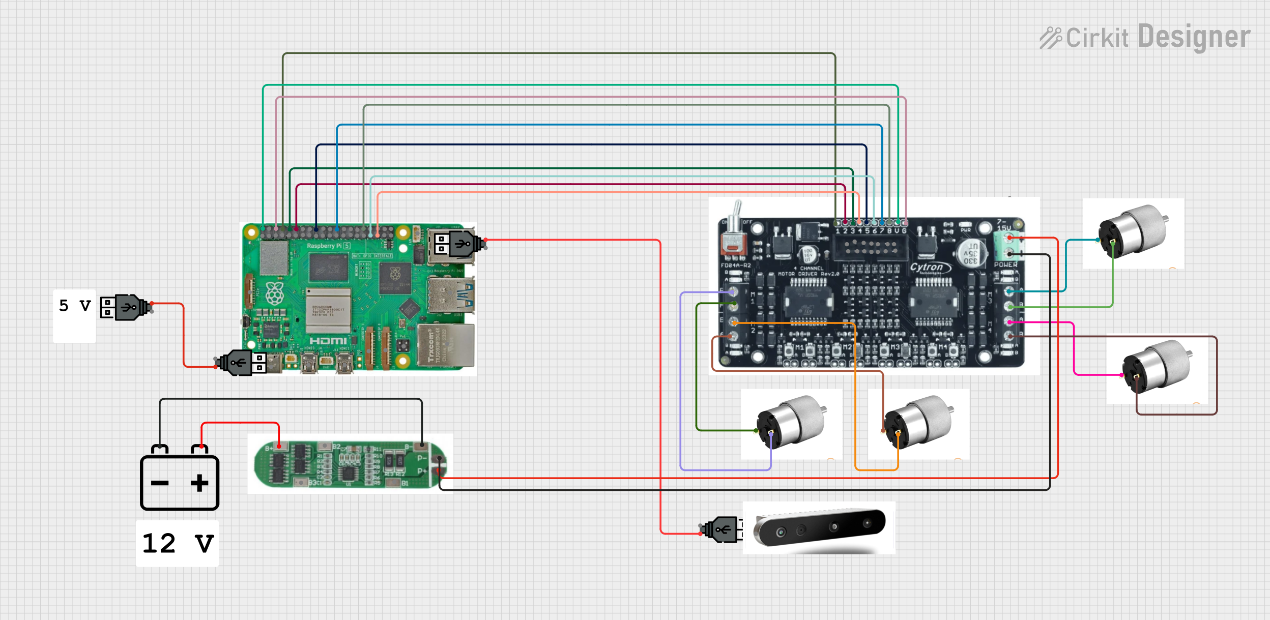
Explore Projects Built with 2 channel CAN FD for Raspberry Pi
Technical Specifications
Key Technical Details
- Supported CAN FD Protocols: ISO 11898-1:2015
- CAN FD Controller: MCP2517FD
- CAN Transceiver: MCP2562FD
- Connection Speed: Up to 8 Mbps for CAN FD
- Operating Voltage: 3.3V (powered from Raspberry Pi)
- Logic Level: 3.3V compatible
- Interface with Raspberry Pi: SPI
- Operating Temperature Range: -40°C to +85°C
Pin Configuration and Descriptions
| Pin Number | Function | Description |
|---|---|---|
| 1 | VDD | Power supply for the module (3.3V from Raspberry Pi) |
| 2 | GND | Ground |
| 3 | SO | SPI MISO (Master In Slave Out) |
| 4 | SI | SPI MOSI (Master Out Slave In) |
| 5 | SCK | SPI Clock |
| 6 | CS | SPI Chip Select |
| 7 | INT | Interrupt pin (active low) |
| 8 | CAN_RX1 | CAN 1 Receive |
| 9 | CAN_TX1 | CAN 1 Transmit |
| 10 | CAN_RX2 | CAN 2 Receive |
| 11 | CAN_TX2 | CAN 2 Transmit |
Usage Instructions
Integrating with Raspberry Pi
Hardware Installation:
- Power off the Raspberry Pi.
- Align the pins of the 2-Channel CAN FD Shield with the GPIO header on the Raspberry Pi and gently press down to connect.
- Ensure that the shield is firmly seated on the Raspberry Pi GPIO header.
Software Configuration:
- Boot up the Raspberry Pi with the latest Raspberry Pi OS installed.
- Open a terminal and run
sudo raspi-config. - Navigate to
Interfacing Optionsand enableSPI. - Update the Raspberry Pi's software by running
sudo apt-get updateandsudo apt-get upgrade.
Driver Installation:
- Install the necessary CAN utilities by running
sudo apt-get install can-utils. - Load the MCP2517FD driver by adding
dtoverlay=mcp2517fd-can0,oscillator=4000000,interrupt=25to/boot/config.txtfor the first channel. - For the second channel, add
dtoverlay=mcp2517fd-can1,oscillator=4000000,interrupt=24. - Reboot the Raspberry Pi.
- Install the necessary CAN utilities by running
Important Considerations and Best Practices
- Ensure that the Raspberry Pi and the 2-Channel CAN FD Shield are not powered while connecting or disconnecting to prevent damage.
- Use proper termination resistors at both ends of the CAN network for reliable communication.
- Keep the CAN bus wiring as short as possible and away from sources of electromagnetic interference.
- Always use shielded twisted-pair cables for CAN bus wiring.
Troubleshooting and FAQs
Common Issues
CAN Interface Not Found:
- Ensure that the SPI interface is enabled on the Raspberry Pi.
- Check that the
dtoverlaylines are correctly added to/boot/config.txt. - Verify the wiring and connections between the Raspberry Pi and the CAN FD Shield.
CAN Communication Errors:
- Confirm that the baud rate and other CAN settings match across all devices on the network.
- Check for proper termination resistors on the CAN network.
- Inspect the CAN bus cables for damage or improper connections.
FAQs
Q: Can I use this shield with any Raspberry Pi model? A: The shield is compatible with Raspberry Pi models that have the 40-pin GPIO header. Check the pinout and physical dimensions to ensure compatibility with your specific model.
Q: How do I know if the shield is working correctly?
A: After setting up the hardware and software, you can use candump can0 or candump can1 to monitor the traffic on the CAN network. If you see data being received, the shield is functioning correctly.
Q: What is the difference between CAN and CAN FD? A: CAN FD (Flexible Data-Rate) is an extension of the original CAN protocol that allows for higher data rates and larger data payloads. It is backward compatible with classic CAN networks.
Q: How do I send CAN FD messages from the Raspberry Pi?
A: You can use the cansend utility to send messages. For example, cansend can0 123#1122334455667788 sends a message with identifier 0x123 and data payload to the first CAN channel.
For further assistance, consult the Raspberry Pi community forums or the manufacturer's support resources.