How to Use Adafruit ATmega32u4 Breakout: Examples, Pinouts, and Specs
Introduction
The Adafruit ATmega32u4 Breakout board is a versatile and powerful microcontroller platform based on the ATmega32u4 chip. This chip is notable for its built-in USB communication, eliminating the need for a secondary processor. This feature allows the ATmega32u4 to appear as a mouse, keyboard, joystick, or other USB device, making it particularly suitable for USB-centric projects. Common applications include DIY keyboards, game controllers, and USB interfaces for robotics and automation projects.
Explore Projects Built with Adafruit ATmega32u4 Breakout
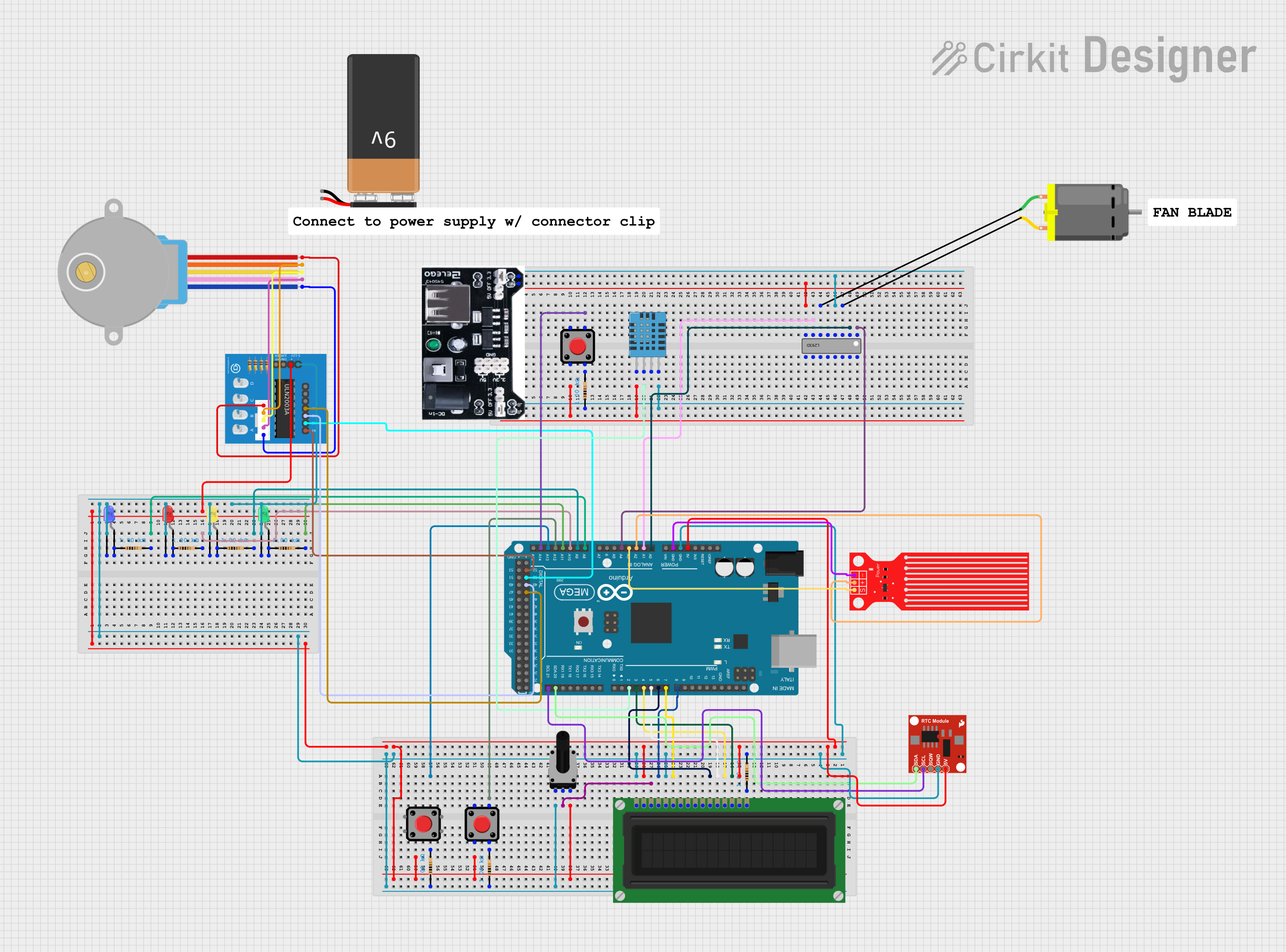

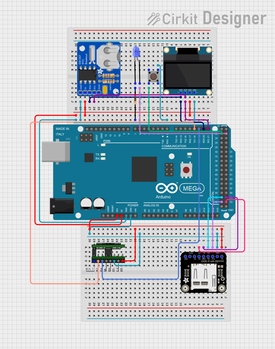
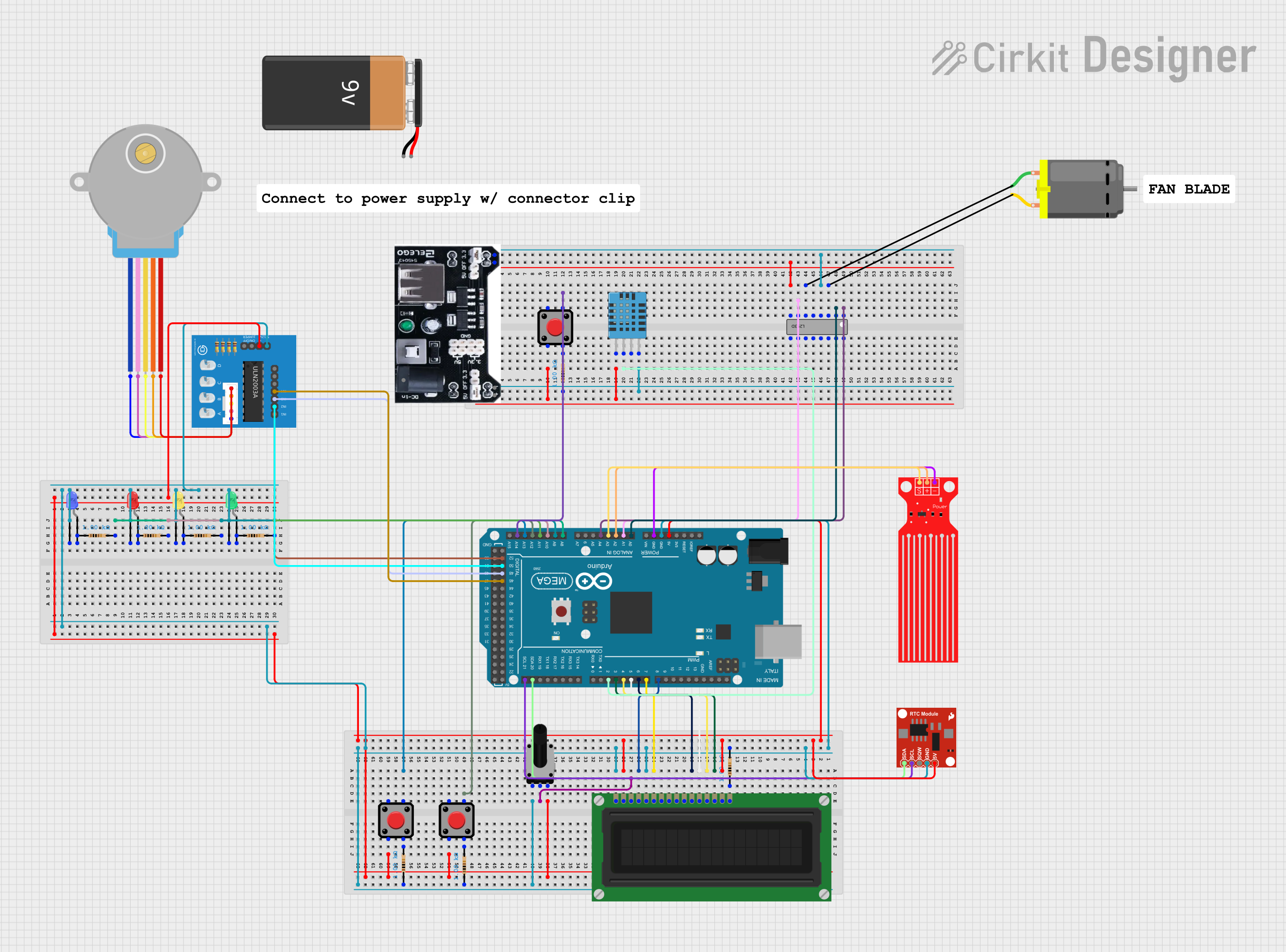
Explore Projects Built with Adafruit ATmega32u4 Breakout
Technical Specifications
Key Features
- Microcontroller: ATmega32u4
- Operating Voltage: 5V
- Input Voltage (recommended): 7-12V
- Input Voltage (limits): 6-16V
- Digital I/O Pins: 20
- PWM Channels: 7
- Analog Input Channels: 12
- DC Current per I/O Pin: 40 mA
- DC Current for 3.3V Pin: 50 mA
- Flash Memory: 32 KB (ATmega32u4) of which 4 KB used by bootloader
- SRAM: 2.5 KB (ATmega32u4)
- EEPROM: 1 KB (ATmega32u4)
- Clock Speed: 16 MHz
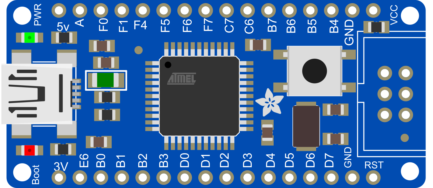
Pin Configuration
| Pin Number | Functionality | Description |
|---|---|---|
| 1 | TXD/INT2 | Serial transmit (can also serve as interrupt source) |
| 2 | RXD/INT3 | Serial receive (can also serve as interrupt source) |
| 3 | SDA/INT1 | I2C Data (can also serve as interrupt source) |
| 4 | SCL/INT0 | I2C Clock (can also serve as interrupt source) |
| 5-12 | Digital Pins 0-7 | General purpose digital I/O pins |
| 13-20 | Digital Pins 8-12, A0-A5 | Digital I/O or Analog Input pins |
| A0-A5 | Analog Inputs | Analog input channels |
| GND | Ground | Ground connection |
| RST | Reset | Resets the microcontroller |
| VCC | Power Supply | Connects to the power supply (5V input) |
Usage Instructions
Integrating with a Circuit
To use the Adafruit ATmega32u4 Breakout board in a circuit:
- Connect the power supply to the VCC and GND pins, ensuring that the voltage is within the recommended limits.
- Interface the board with other components using the digital I/O and analog input pins as required by your project.
- If using I2C or serial communication, connect the SDA and SCL or TXD and RXD pins to the corresponding pins on the other device.
- To program the board, connect it to a computer using a micro USB cable.
Programming
The ATmega32u4 can be programmed using the Arduino IDE:
- Download and install the Arduino IDE from the official Arduino website.
- Connect the ATmega32u4 Breakout board to your computer using a micro USB cable.
- Select "Arduino Leonardo" from the Tools > Board menu (the ATmega32u4 is compatible with the Leonardo bootloader).
- Write your sketch and upload it to the board using the IDE.
Best Practices
- Always disconnect the board from power sources before making or altering connections.
- Use a current-limiting resistor with LEDs and other sensitive components to prevent damage.
- Avoid exposing the board to static electricity, which can damage the microcontroller.
- Ensure that all connections are secure to prevent intermittent behavior.
Troubleshooting and FAQs
Common Issues
- Board not recognized by the computer: Ensure that the micro USB cable is properly connected and that the cable is not damaged. Try using a different cable or port if the problem persists.
- Sketch not uploading: Check that the correct board and port are selected in the Arduino IDE. Press the reset button on the board and try uploading again.
- Unexpected behavior in circuits: Verify that all connections are correct and that the power supply is within the specified limits. Check for shorts or open circuits.
FAQs
Q: Can I use the ATmega32u4 Breakout board as a USB HID device? A: Yes, the ATmega32u4 can emulate a USB Human Interface Device (HID), such as a keyboard or mouse.
Q: What should I do if I accidentally set the wrong fuse bits? A: You will need an ISP (In-System Programmer) to reset the fuse bits to their correct settings.
Q: How can I extend the number of I/O pins? A: You can use shift registers or I/O expanders to increase the number of available pins.
For further assistance, consult the Adafruit forums or the extensive online community resources.
Example Code for Arduino UNO
Below is a simple example of how to blink an LED connected to pin 13 of the Adafruit ATmega32u4 Breakout board using the Arduino IDE.
// Define the LED pin
const int ledPin = 13;

// the setup routine runs once when you press reset:
void setup() {
  // initialize the digital pin as an output.
  pinMode(ledPin, OUTPUT);
}

// the loop routine runs over and over again forever:
void loop() {
  digitalWrite(ledPin, HIGH);   // turn the LED on (HIGH is the voltage level)
  delay(1000);                  // wait for a second
  digitalWrite(ledPin, LOW);    // turn the LED off by making the voltage LOW
  delay(1000);                  // wait for a second
}
Remember to select "Arduino Leonardo" as the board type when programming the ATmega32u4 Breakout board, as it shares the same bootloader.