
How to Use Shift Register Breakout - 74HC595: Examples, Pinouts, and Specs
 Design with Shift Register Breakout - 74HC595 in Cirkit Designer
Introduction
The Shift Register Breakout - 74HC595 (Manufacturer Part ID: BOB-10680) by SparkFun Electronics is an 8-bit shift register with output latches. It is designed to expand the number of output pins available from a microcontroller. By using serial data input and parallel data output, this component allows you to control multiple devices, such as LEDs, with minimal pin usage.
This breakout board is particularly useful in applications where microcontroller pins are limited, such as:
- Driving multiple LEDs or 7-segment displays
- Controlling relays or other digital outputs
- Expanding GPIO capabilities in embedded systems
Explore Projects Built with Shift Register Breakout - 74HC595
 Open Project in Cirkit Designer
 Open Project in Cirkit Designer
 Open Project in Cirkit Designer
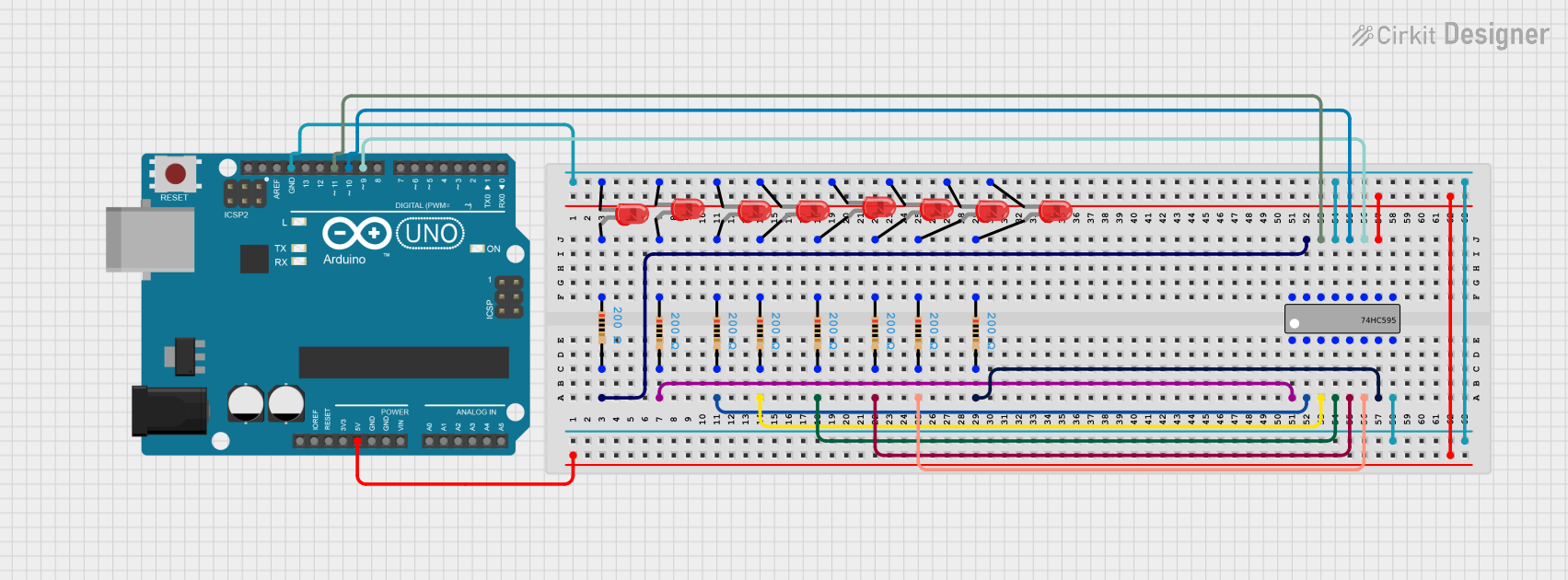 Open Project in Cirkit Designer
Explore Projects Built with Shift Register Breakout - 74HC595
Open Project in Cirkit DesignerOpen Project in Cirkit DesignerOpen Project in Cirkit DesignerOpen Project in Cirkit DesignerTechnical Specifications
Below are the key technical details and pin configuration for the Shift Register Breakout - 74HC595:
Key Technical Details
| Parameter | Value |
|---|---|
| Supply Voltage (Vcc) | 2V to 6V |
| Logic Input Voltage | 0V to Vcc |
| Maximum Clock Frequency | 25 MHz (at 5V Vcc) |
| Output Current (per pin) | ±6 mA |
| Total Output Current | 70 mA (maximum) |
| Operating Temperature | -40°C to +125°C |
| Package Type | Breakout board with 74HC595 |
Pin Configuration and Descriptions
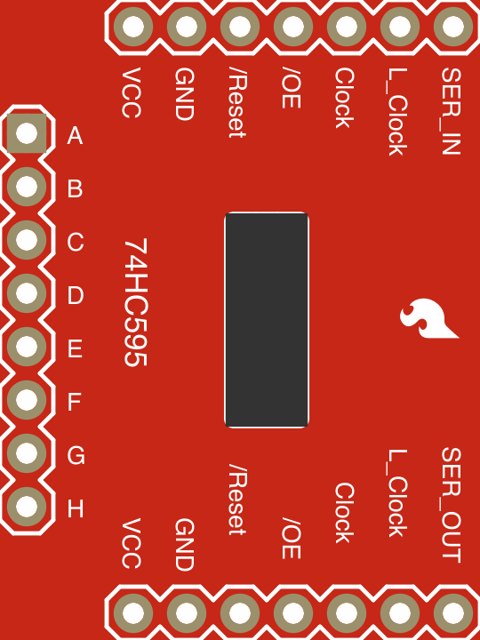
The breakout board exposes the following pins for easy interfacing:
| Pin Name | Pin Number | Description |
|---|---|---|
| Vcc | 1 | Power supply input (2V to 6V). Connect to the microcontroller's 5V or 3.3V. |
| GND | 2 | Ground connection. |
| SER | 3 | Serial data input. Used to send data to the shift register. |
| SRCLK | 4 | Shift register clock input. Data is shifted on the rising edge. |
| RCLK | 5 | Latch clock input. Transfers data from the shift register to the output. |
| OE | 6 | Output enable (active low). Pull low to enable outputs. |
| SRCLR | 7 | Shift register clear (active low). Clears the shift register when low. |
| Q0-Q7 | 8-15 | Parallel data outputs. These are the 8 output pins of the shift register. |
Usage Instructions
How to Use the Component in a Circuit
- Power the Breakout Board: Connect the
Vccpin to a 5V or 3.3V power source and theGNDpin to ground. - Connect Control Pins:
- Connect the
SERpin to the microcontroller's data output pin. - Connect the
SRCLKpin to a clock pin on the microcontroller. - Connect the
RCLKpin to another control pin on the microcontroller.
- Connect the
- Enable Outputs: Pull the
OEpin low to enable the outputs. If left high, the outputs will remain disabled. - Send Data:
- Use the
SERpin to send serial data to the shift register. - Pulse the
SRCLKpin to shift the data into the register. - Pulse the
RCLKpin to latch the data to the output pins (Q0-Q7).
- Use the
Important Considerations and Best Practices
- Current Limiting: If driving LEDs, use appropriate resistors to limit current through each output pin.
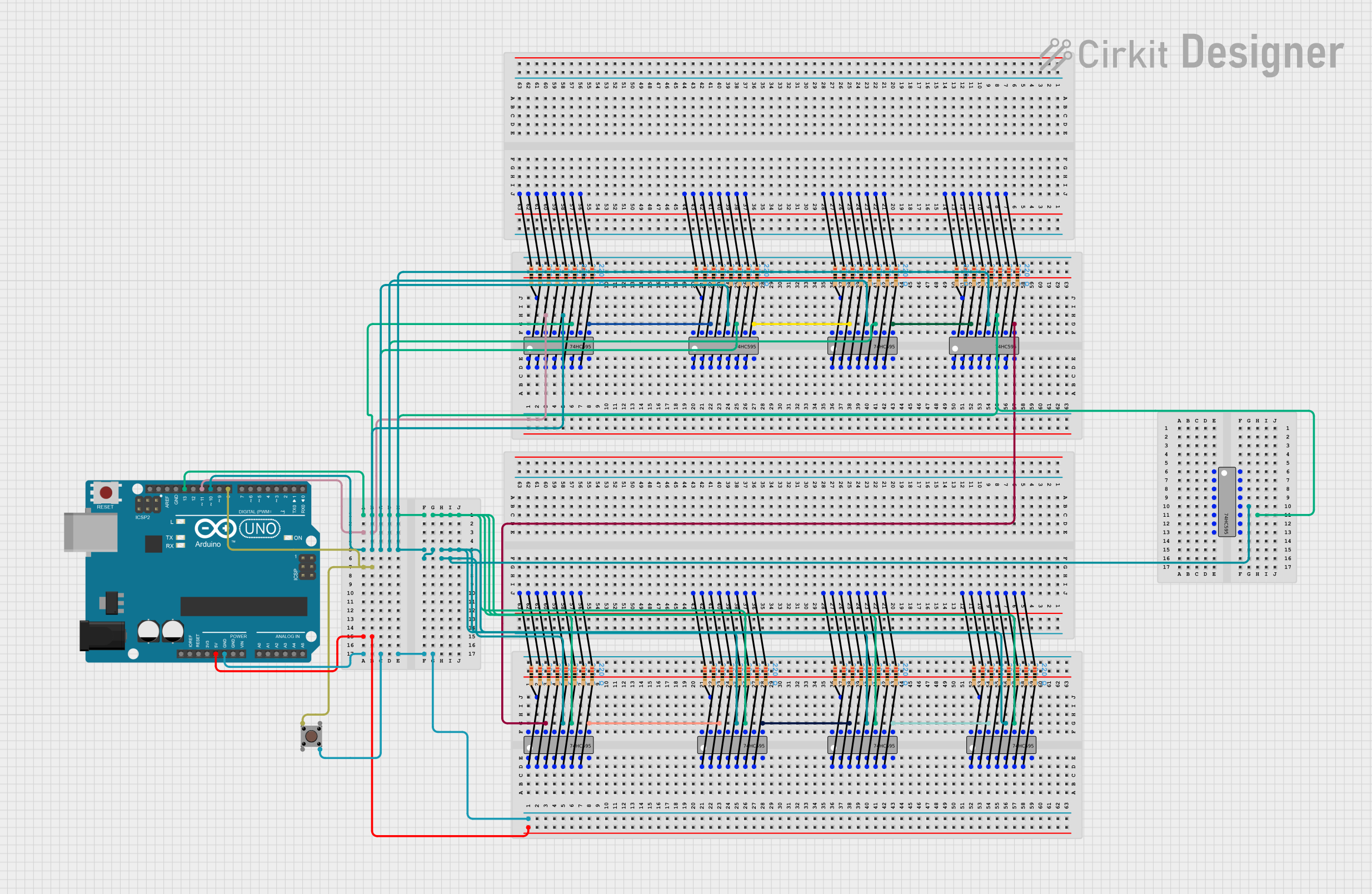
- Cascading: Multiple 74HC595 shift registers can be cascaded to control more outputs. Connect the
Q7S(serial out) pin of the first register to theSERpin of the next register. - Decoupling Capacitor: Place a 0.1 µF capacitor between
VccandGNDto reduce noise and stabilize the power supply.
Example Code for Arduino UNO
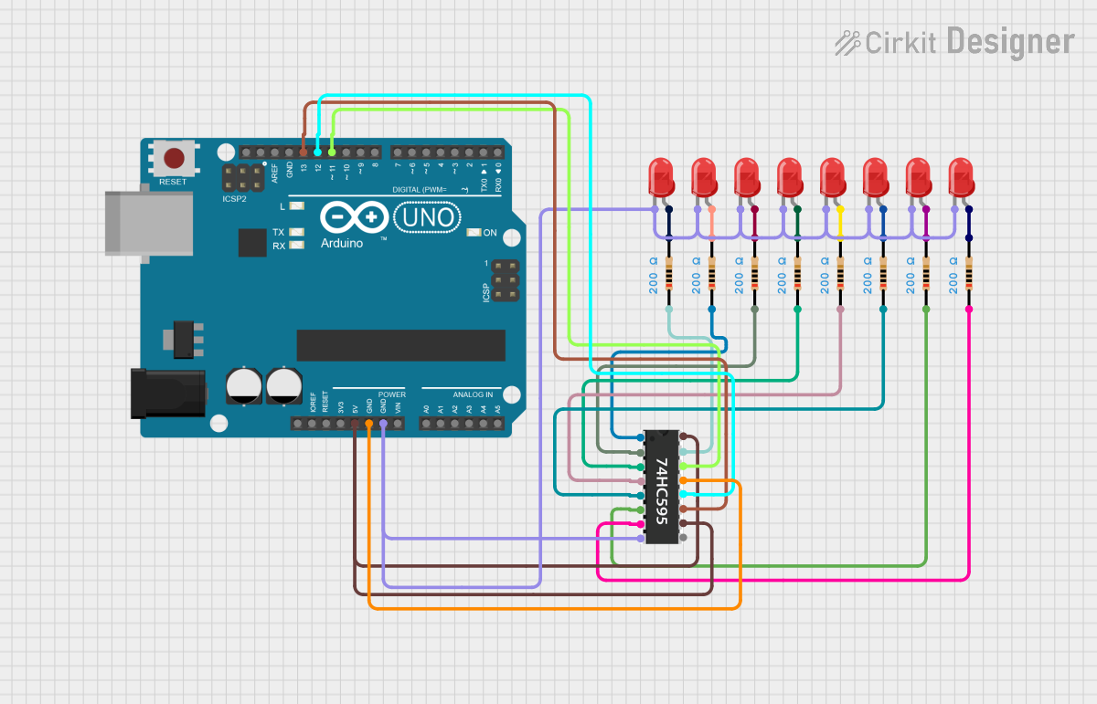
Below is an example of how to use the Shift Register Breakout - 74HC595 with an Arduino UNO to control 8 LEDs:
// Pin definitions for the 74HC595
const int dataPin = 2;   // SER pin on the 74HC595
const int clockPin = 3;  // SRCLK pin on the 74HC595
const int latchPin = 4;  // RCLK pin on the 74HC595

void setup() {
  // Set pin modes
  pinMode(dataPin, OUTPUT);
  pinMode(clockPin, OUTPUT);
  pinMode(latchPin, OUTPUT);
}

void loop() {
  // Example pattern to display on LEDs
  byte ledPattern = 0b10101010; // Alternating LEDs on/off

  // Send the pattern to the shift register
  digitalWrite(latchPin, LOW);  // Disable latch to load data
  shiftOut(dataPin, clockPin, MSBFIRST, ledPattern); // Send data
  digitalWrite(latchPin, HIGH); // Enable latch to update outputs

  delay(500); // Wait for 500ms

  // Turn off all LEDs
  digitalWrite(latchPin, LOW);
  shiftOut(dataPin, clockPin, MSBFIRST, 0b00000000); // All LEDs off
  digitalWrite(latchPin, HIGH);

  delay(500); // Wait for 500ms
}
Troubleshooting and FAQs
Common Issues and Solutions
Outputs Not Working:
- Ensure the
OEpin is pulled low to enable the outputs. - Verify that the
VccandGNDconnections are correct and stable. - Check for loose or incorrect wiring of the control pins (
SER,SRCLK,RCLK).
- Ensure the
Incorrect Output Data:
- Ensure the
SRCLKandRCLKpins are pulsed correctly. Data is shifted on the rising edge ofSRCLKand latched on the rising edge ofRCLK. - Verify the data being sent to the
SERpin matches the intended output pattern.
- Ensure the
Flickering LEDs:
- Add a decoupling capacitor (0.1 µF) between
VccandGNDto stabilize the power supply. - Ensure the microcontroller's clock speed and timing are appropriate for the shift register.
- Add a decoupling capacitor (0.1 µF) between
FAQs
Q: Can I cascade multiple 74HC595 shift registers?
A: Yes, you can cascade multiple shift registers by connecting the Q7S (serial out) pin of one register to the SER (serial in) pin of the next register. This allows you to control more outputs with the same control pins.
Q: What is the maximum number of LEDs I can control with one 74HC595?
A: The 74HC595 has 8 output pins (Q0-Q7), so you can control up to 8 LEDs. For more LEDs, cascade additional shift registers.
Q: Can I use the 74HC595 with a 3.3V microcontroller?
A: Yes, the 74HC595 operates with a supply voltage range of 2V to 6V, making it compatible with both 3.3V and 5V systems.
Q: What happens if I leave the OE pin floating?
A: The OE pin must be pulled low to enable the outputs. If left floating, the outputs may remain disabled or behave unpredictably.