How to Use TECNOULAB MAX31865 RTD Platinum Resistance Temperature Detector Module PT100 - PT1000: Examples, Pinouts, and Specs
Introduction
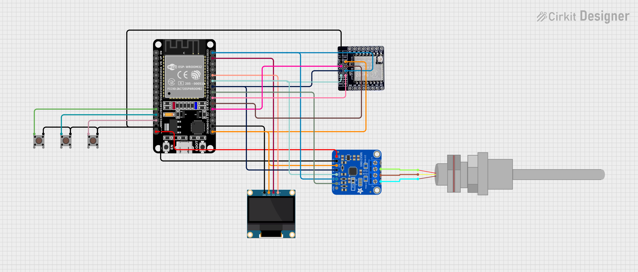
The TECNOULAB MAX31865 RTD module is a precision temperature sensor interface designed to work with PT100 or PT1000 resistance temperature detectors (RTDs). It utilizes the MAX31865 chip to convert the RTD's resistance into a digital signal, enabling accurate temperature measurements. This module is widely used in industrial, scientific, and DIY applications where precise temperature monitoring is required.
Explore Projects Built with TECNOULAB MAX31865 RTD Platinum Resistance Temperature Detector Module PT100 - PT1000
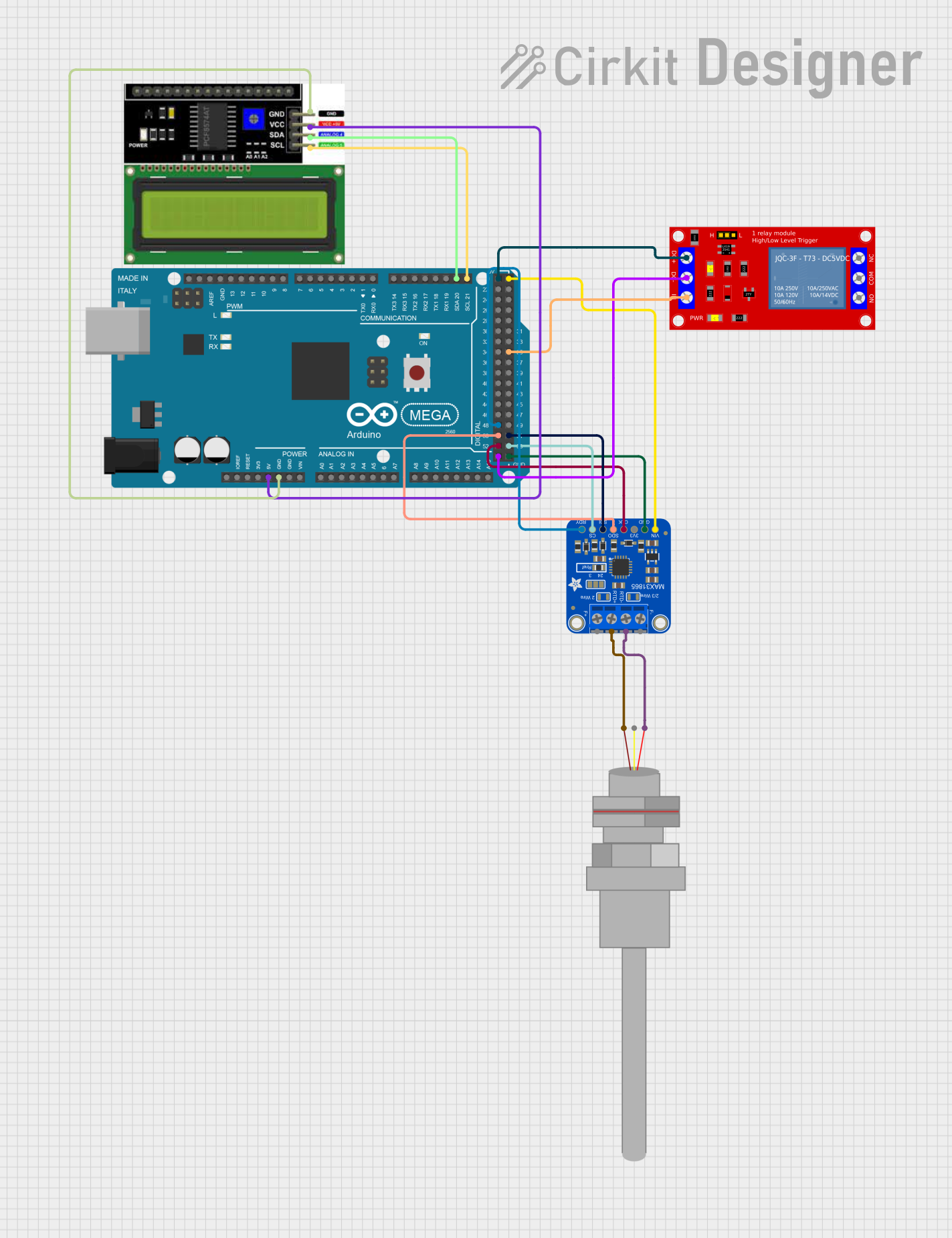
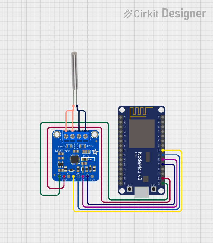
Explore Projects Built with TECNOULAB MAX31865 RTD Platinum Resistance Temperature Detector Module PT100 - PT1000
Common Applications
- Industrial process control and monitoring
- Laboratory-grade temperature measurement
- HVAC systems
- Environmental monitoring
- DIY electronics projects requiring high-accuracy temperature sensing
Technical Specifications
Key Technical Details
- Chipset: MAX31865
- Supported RTDs: PT100 (100Ω) and PT1000 (1000Ω)
- Operating Voltage: 3.3V or 5V (logic level compatible)
- Communication Protocol: SPI (Serial Peripheral Interface)
- Temperature Range: -200°C to +850°C (dependent on RTD type)
- Accuracy: ±0.5°C (typical, depending on RTD and calibration)
- Input Impedance: High impedance for accurate resistance measurement
- Fault Detection: Open circuit, short circuit, and over/under-voltage detection
- Dimensions: Compact PCB design for easy integration
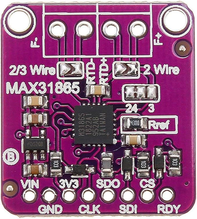
Pin Configuration and Descriptions
The TECNOULAB MAX31865 module has the following pinout:
| Pin | Name | Description |
|---|---|---|
| 1 | VCC | Power supply input (3.3V or 5V, depending on system logic level). |
| 2 | GND | Ground connection. |
| 3 | SDO/MISO | SPI data output (Master In Slave Out). |
| 4 | SDI/MOSI | SPI data input (Master Out Slave In). |
| 5 | SCK | SPI clock input. |
| 6 | CS | Chip Select (active low, used to enable communication with the module). |
| 7 | RTD+ | Positive terminal for connecting the RTD sensor. |
| 8 | RTD- | Negative terminal for connecting the RTD sensor. |
Usage Instructions
How to Use the Component in a Circuit
- Power the Module: Connect the VCC pin to a 3.3V or 5V power source and the GND pin to ground.
- Connect the RTD Sensor: Attach the PT100 or PT1000 sensor to the RTD+ and RTD- terminals.
- SPI Communication: Connect the SDO, SDI, SCK, and CS pins to the corresponding SPI pins on your microcontroller or development board.
- Configure the MAX31865: Use software to set the module for PT100 or PT1000 operation and configure the desired fault detection and filtering options.
- Read Temperature Data: Use SPI commands to read the resistance value and convert it to temperature using the RTD's characteristic equation or a library.
Important Considerations and Best Practices
- Ensure the RTD sensor is properly connected to avoid open or short circuits.
- Use shielded cables for the RTD sensor in noisy environments to minimize interference.
- Calibrate the system if high accuracy is required, especially for critical applications.
- Avoid exceeding the module's voltage and temperature limits to prevent damage.
- Use pull-up resistors on the SPI lines if required by your microcontroller.
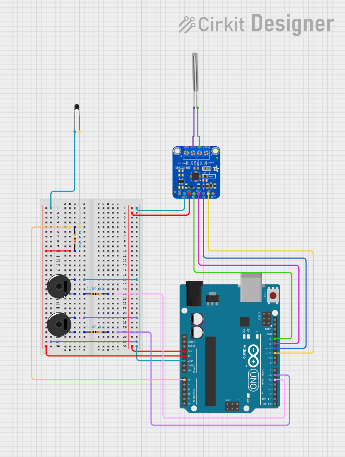
Example Code for Arduino UNO
Below is an example of how to use the TECNOULAB MAX31865 module with an Arduino UNO:
#include <SPI.h>
#include <Adafruit_MAX31865.h>

// Define the SPI pins for the MAX31865 module
#define MAX31865_CS 10  // Chip Select pin
#define MAX31865_MOSI 11  // Master Out Slave In pin
#define MAX31865_MISO 12  // Master In Slave Out pin
#define MAX31865_SCK 13  // SPI Clock pin

// Create an instance of the MAX31865 library for a PT100 sensor
Adafruit_MAX31865 max31865 = Adafruit_MAX31865(MAX31865_CS);

// Uncomment the following line for PT1000 sensors
// Adafruit_MAX31865 max31865 = Adafruit_MAX31865(MAX31865_CS, 1000.0);

void setup() {
  Serial.begin(9600);
  Serial.println("MAX31865 RTD Module Test");

  // Initialize the MAX31865 module
  if (!max31865.begin(MAX31865_3WIRE)) {
    // MAX31865_3WIRE is for 3-wire RTDs; use MAX31865_2WIRE or MAX31865_4WIRE
    // for other configurations.
    Serial.println("Failed to initialize MAX31865. Check connections!");
    while (1);
  }
}

void loop() {
  // Read the temperature in Celsius
  float temperature = max31865.temperature(100.0, 430.0);
  // 100.0 is the reference resistance for PT100; adjust for PT1000 if needed.
  // 430.0 is the RTD's resistance at 0°C; adjust for your RTD type.

  Serial.print("Temperature: ");
  Serial.print(temperature);
  Serial.println(" °C");

  delay(1000);  // Wait 1 second before the next reading
}
Notes on the Code
- The
Adafruit_MAX31865library is used for easy communication with the MAX31865 module. Install it via the Arduino Library Manager. - Adjust the RTD type and wiring configuration in the
begin()andtemperature()functions as needed.
Troubleshooting and FAQs
Common Issues and Solutions
No Temperature Reading:
- Verify the SPI connections and ensure the correct pins are used.
- Check the RTD sensor wiring for loose or incorrect connections.
Incorrect Temperature Values:
- Ensure the correct RTD type (PT100 or PT1000) is configured in the software.
- Calibrate the system if necessary to improve accuracy.
Module Not Detected:
- Confirm the CS pin is correctly connected and pulled low during communication.
- Check the power supply voltage and ensure it matches the module's requirements.
Fault Detection Errors:
- Inspect the RTD sensor for open or short circuits.
- Verify the RTD sensor's resistance matches the expected range.
FAQs
Q: Can I use this module with a 2-wire RTD?
A: Yes, the MAX31865 supports 2-wire, 3-wire, and 4-wire RTDs. Configure the wiring and software accordingly.
Q: What is the maximum cable length for the RTD sensor?
A: The maximum cable length depends on the environment and cable type. Use shielded cables for longer distances to reduce noise.
Q: Is the module compatible with 3.3V logic microcontrollers?
A: Yes, the module works with both 3.3V and 5V logic levels.
Q: How do I improve measurement accuracy?
A: Use high-quality RTDs, minimize noise, and calibrate the system for your specific application.