
How to Use 120V AC to 24V DC 600W: Examples, Pinouts, and Specs
 Design with 120V AC to 24V DC 600W in Cirkit Designer
Introduction
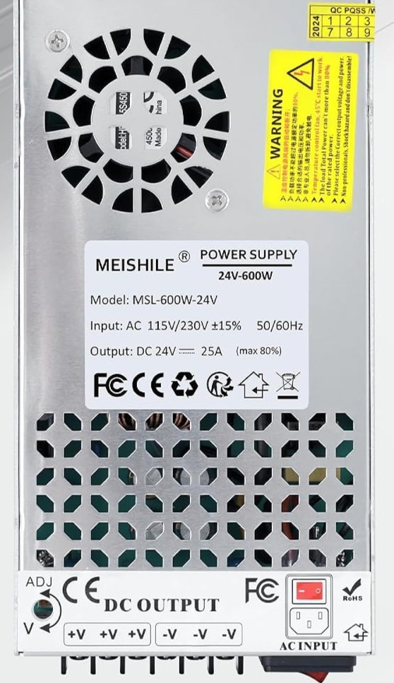
The 120V AC to 24V DC 600W power supply unit is a high-performance device designed to convert standard 120V alternating current (AC) into 24V direct current (DC). With a maximum output power of 600 watts, this power supply is ideal for powering medium to high-power electronic devices and systems. It is commonly used in industrial automation, LED lighting systems, motor drives, and other applications requiring a stable and reliable DC power source.
Explore Projects Built with 120V AC to 24V DC 600W
 Open Project in Cirkit Designer
 Open Project in Cirkit Designer
 Open Project in Cirkit Designer
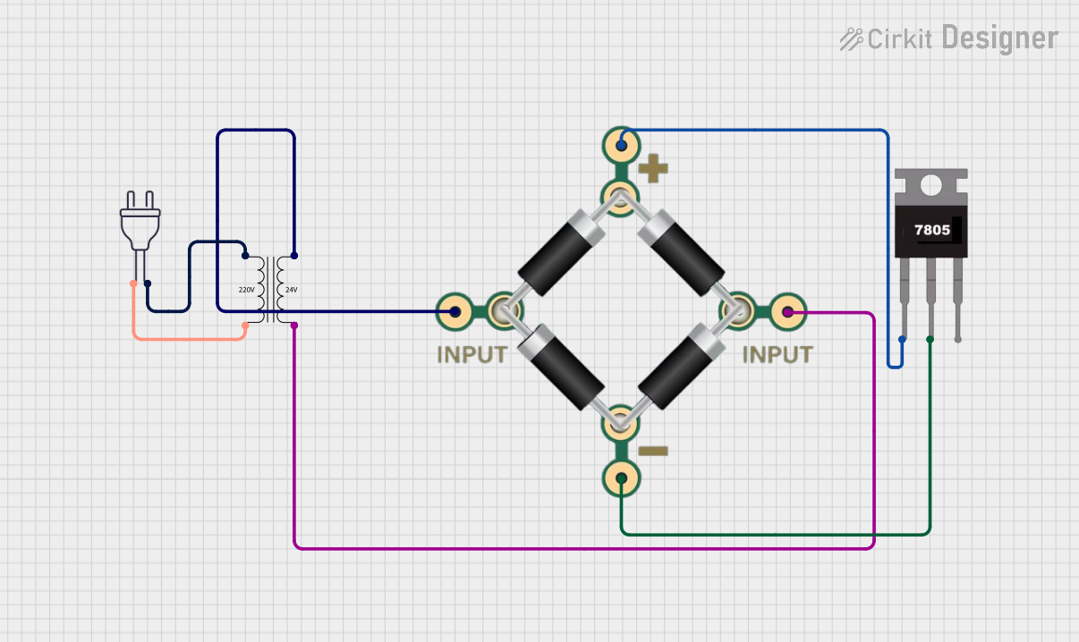 Open Project in Cirkit Designer
Explore Projects Built with 120V AC to 24V DC 600W
Open Project in Cirkit DesignerOpen Project in Cirkit DesignerOpen Project in Cirkit DesignerOpen Project in Cirkit DesignerCommon Applications
- Industrial automation equipment
- LED lighting systems
- CNC machines and motor drives
- Battery charging systems
- Telecommunications equipment
- Laboratory and testing setups
Technical Specifications
Below are the key technical details of the 120V AC to 24V DC 600W power supply:
| Parameter | Specification |
|---|---|
| Input Voltage Range | 100V - 130V AC |
| Output Voltage | 24V DC |
| Maximum Output Power | 600W |
| Maximum Output Current | 25A |
| Efficiency | ≥ 85% |
| Frequency Range | 50Hz - 60Hz |
| Operating Temperature | -10°C to +50°C |
| Cooling Method | Forced air cooling (built-in fan) |
| Protection Features | Overload, overvoltage, short circuit |
| Dimensions | 215mm x 115mm x 50mm |
| Weight | ~1.2 kg |
Pin Configuration and Descriptions
The power supply unit typically has the following input and output terminals:
Input Terminals
| Pin | Label | Description |
|---|---|---|
| L | Line | Connect to the live wire of the AC input. |
| N | Neutral | Connect to the neutral wire of the AC input. |
| GND | Ground | Connect to the earth/ground wire for safety. |
Output Terminals
| Pin | Label | Description |
|---|---|---|
| V+ | Positive | Positive terminal for 24V DC output. |
| V- | Negative | Negative terminal for 24V DC output. |
Usage Instructions
How to Use the Component in a Circuit
- Safety First: Ensure the power supply is disconnected from the AC mains before wiring.
- Input Connection:
- Connect the
Lterminal to the live wire of the AC mains. - Connect the
Nterminal to the neutral wire of the AC mains. - Connect the
GNDterminal to the earth/ground wire for safety.
- Connect the
- Output Connection:
- Connect the
V+terminal to the positive input of your load or circuit. - Connect the
V-terminal to the negative input of your load or circuit.
- Connect the
- Power On:
- After verifying all connections, plug the power supply into the AC mains and switch it on.
- The built-in fan will activate, and the output terminals will provide a stable 24V DC.
Important Considerations and Best Practices
- Load Requirements: Ensure the connected load does not exceed the maximum output power of 600W or the maximum current of 25A.
- Ventilation: Install the power supply in a well-ventilated area to prevent overheating.
- Grounding: Properly ground the unit to avoid electrical hazards.
- Polarity: Double-check the polarity of the output connections to prevent damage to your devices.
- Fuse Protection: Use an appropriate fuse on the input side for added safety.
Example: Connecting to an Arduino UNO
The 120V AC to 24V DC power supply can be used to power an Arduino UNO indirectly by stepping down the 24V DC to 5V DC using a DC-DC buck converter. Below is an example setup:
- Connect the
V+andV-terminals of the power supply to the input of a DC-DC buck converter. - Adjust the buck converter to output 5V DC.
- Connect the 5V output of the buck converter to the Arduino UNO's
5VandGNDpins.
Sample Arduino Code
// Example code to blink an LED connected to pin 13 of the Arduino UNO
// Ensure the Arduino is powered via the 5V output of the buck converter

void setup() {
  pinMode(13, OUTPUT); // Set pin 13 as an output pin
}

void loop() {
  digitalWrite(13, HIGH); // Turn the LED on
  delay(1000);            // Wait for 1 second
  digitalWrite(13, LOW);  // Turn the LED off
  delay(1000);            // Wait for 1 second
}
Troubleshooting and FAQs
Common Issues and Solutions
No Output Voltage:
- Cause: Incorrect wiring or no AC input.
- Solution: Verify the AC input connections and ensure the power supply is receiving power.
Overheating:
- Cause: Insufficient ventilation or excessive load.
- Solution: Ensure proper airflow around the unit and reduce the load if it exceeds 600W.
Output Voltage Fluctuations:
- Cause: Unstable AC input or overloaded output.
- Solution: Check the AC input voltage and ensure the load is within the rated capacity.
Fan Not Working:
- Cause: Faulty fan or blocked ventilation.
- Solution: Inspect the fan for obstructions or damage and replace if necessary.
FAQs
Q1: Can this power supply be used with 220V AC input?
A1: No, this power supply is designed for 120V AC input only. Using it with 220V AC may damage the unit.
Q2: Is the output voltage adjustable?
A2: Some models may have a small potentiometer to fine-tune the output voltage. Check the product manual for details.
Q3: Can I connect multiple power supplies in parallel for higher current?
A3: It is not recommended unless the power supplies are specifically designed for parallel operation.
Q4: What type of fuse should I use for input protection?
A4: Use a fuse rated for 120V AC and slightly above the maximum input current (e.g., 10A).