How to Use Servo (G/V/PWM): Examples, Pinouts, and Specs
Introduction
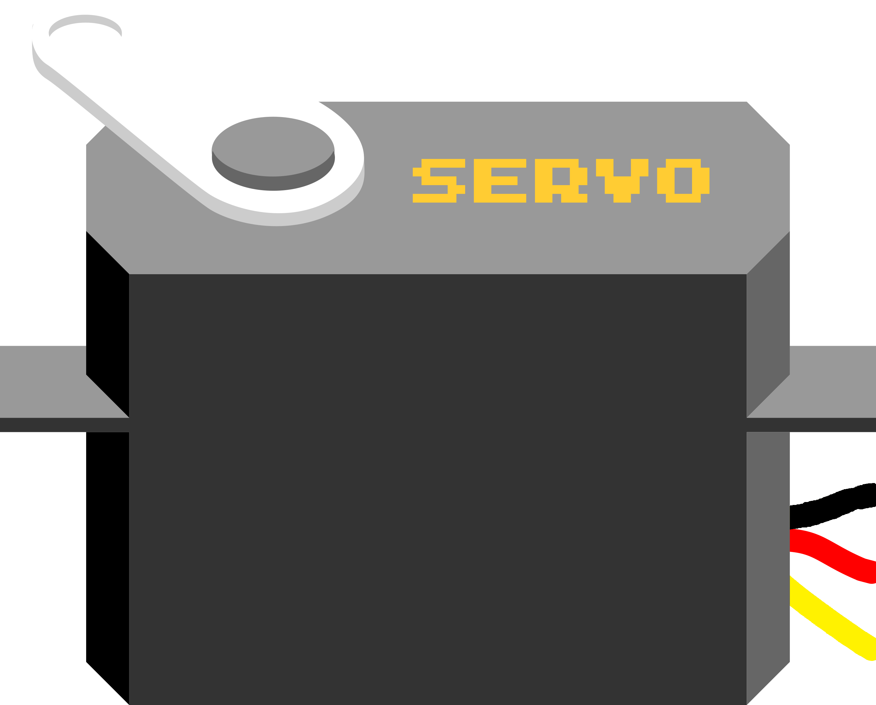
A servo motor is a compact and versatile electromechanical device designed for precise angular positioning. The Servo (G/V/PWM) model can be controlled using General (G), Voltage (V), or Pulse Width Modulation (PWM) signals, making it suitable for a wide range of applications. It is widely used in robotics, automation systems, RC vehicles, and other projects requiring accurate rotational control.
Explore Projects Built with Servo (G/V/PWM)

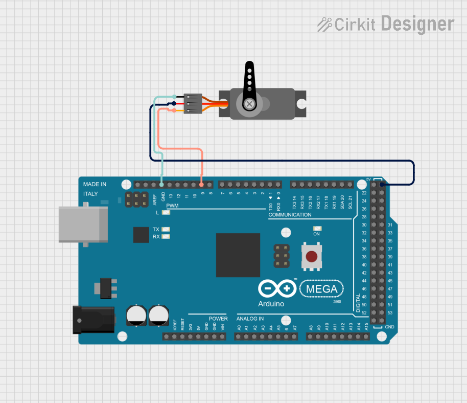
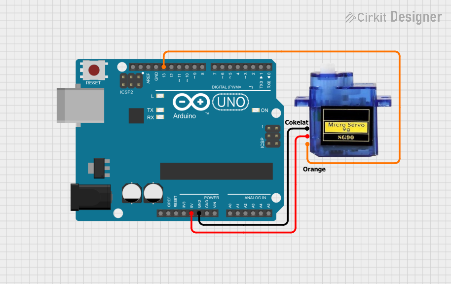
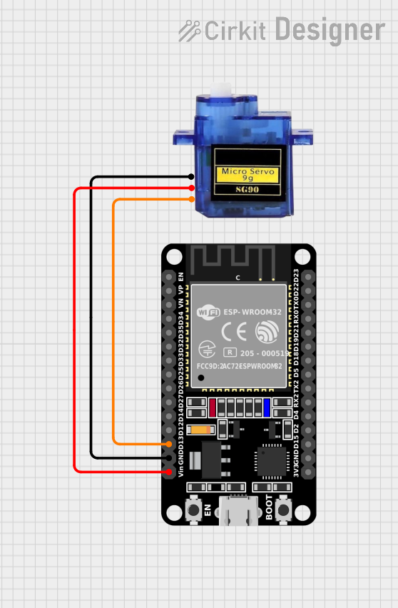
Explore Projects Built with Servo (G/V/PWM)
Common Applications:
- Robotic arms and grippers
- RC cars, boats, and planes
- Automated camera gimbals
- Industrial automation systems
- DIY electronics and Arduino projects
Technical Specifications
Key Technical Details:
| Parameter | Value |
|---|---|
| Operating Voltage | 4.8V to 6.0V |
| Stall Torque | 1.8 kg·cm (4.8V) / 2.2 kg·cm (6.0V) |
| Operating Speed | 0.12 sec/60° (4.8V) / 0.10 sec/60° (6.0V) |
| Control Signal | PWM (Pulse Width Modulation) |
| PWM Pulse Range | 500 µs to 2500 µs |
| Angle Range | 0° to 180° |
| Idle Current | 10 mA |
| Maximum Current | 1.5 A |
| Dimensions | 40 mm x 20 mm x 36 mm |
| Weight | 45 g |
Pin Configuration:
| Pin Number | Pin Name | Description |
|---|---|---|
| 1 | GND | Ground connection for the servo motor |
| 2 | VCC | Power supply input (4.8V to 6.0V) |
| 3 | PWM Signal | Control signal input for angular positioning |
Usage Instructions
How to Use the Servo in a Circuit:
- Power the Servo: Connect the VCC pin to a 5V or 6V power source and the GND pin to the ground of your circuit.
- Control Signal: Use a microcontroller (e.g., Arduino UNO) to send a PWM signal to the PWM Signal pin. The width of the PWM pulse determines the angular position of the servo.
- A 1 ms pulse typically corresponds to 0°.
- A 1.5 ms pulse corresponds to 90° (neutral position).
- A 2 ms pulse corresponds to 180°.
- Load Considerations: Avoid exceeding the torque rating of the servo to prevent damage.
- External Power Source: If the servo draws significant current, use an external power source instead of powering it directly from the microcontroller.
Arduino UNO Example Code:
#include <Servo.h> // Include the Servo library

Servo myServo; // Create a Servo object to control the servo motor

void setup() {
  myServo.attach(9); // Attach the servo to pin 9 on the Arduino UNO
}

void loop() {
  myServo.write(0); // Move the servo to 0 degrees
  delay(1000); // Wait for 1 second

  myServo.write(90); // Move the servo to 90 degrees
  delay(1000); // Wait for 1 second

  myServo.write(180); // Move the servo to 180 degrees
  delay(1000); // Wait for 1 second
}
Best Practices:
- Use a capacitor across the power supply to stabilize voltage and reduce noise.
- Avoid stalling the servo for extended periods, as it may overheat.
- Use a separate power supply for the servo if it draws more current than the microcontroller can provide.
Troubleshooting and FAQs
Common Issues and Solutions:
Servo Not Moving:
- Cause: Incorrect wiring or insufficient power supply.
- Solution: Double-check the connections and ensure the power supply meets the voltage and current requirements.
Servo Jitters or Vibrations:
- Cause: Electrical noise or unstable power supply.
- Solution: Add a decoupling capacitor (e.g., 100 µF) across the power supply.
Servo Overheating:
- Cause: Prolonged stalling or excessive load.
- Solution: Reduce the load or avoid stalling the servo for long durations.
Limited Range of Motion:
- Cause: Incorrect PWM signal range.
- Solution: Verify the PWM pulse width and ensure it is within the 500 µs to 2500 µs range.
FAQs:
Q: Can I power the servo directly from the Arduino UNO?
A: While possible, it is not recommended for high-current applications. Use an external power source for better performance.Q: What happens if I send a PWM signal outside the specified range?
A: The servo may not respond correctly or could attempt to move beyond its physical limits, potentially causing damage.Q: Can I control multiple servos with one Arduino?
A: Yes, you can control multiple servos using different PWM-capable pins, but ensure the power supply can handle the combined current draw.
By following this documentation, you can effectively integrate and troubleshoot the Servo (G/V/PWM) in your projects.