How to Use V_REG_LD1085: Examples, Pinouts, and Specs
Introduction
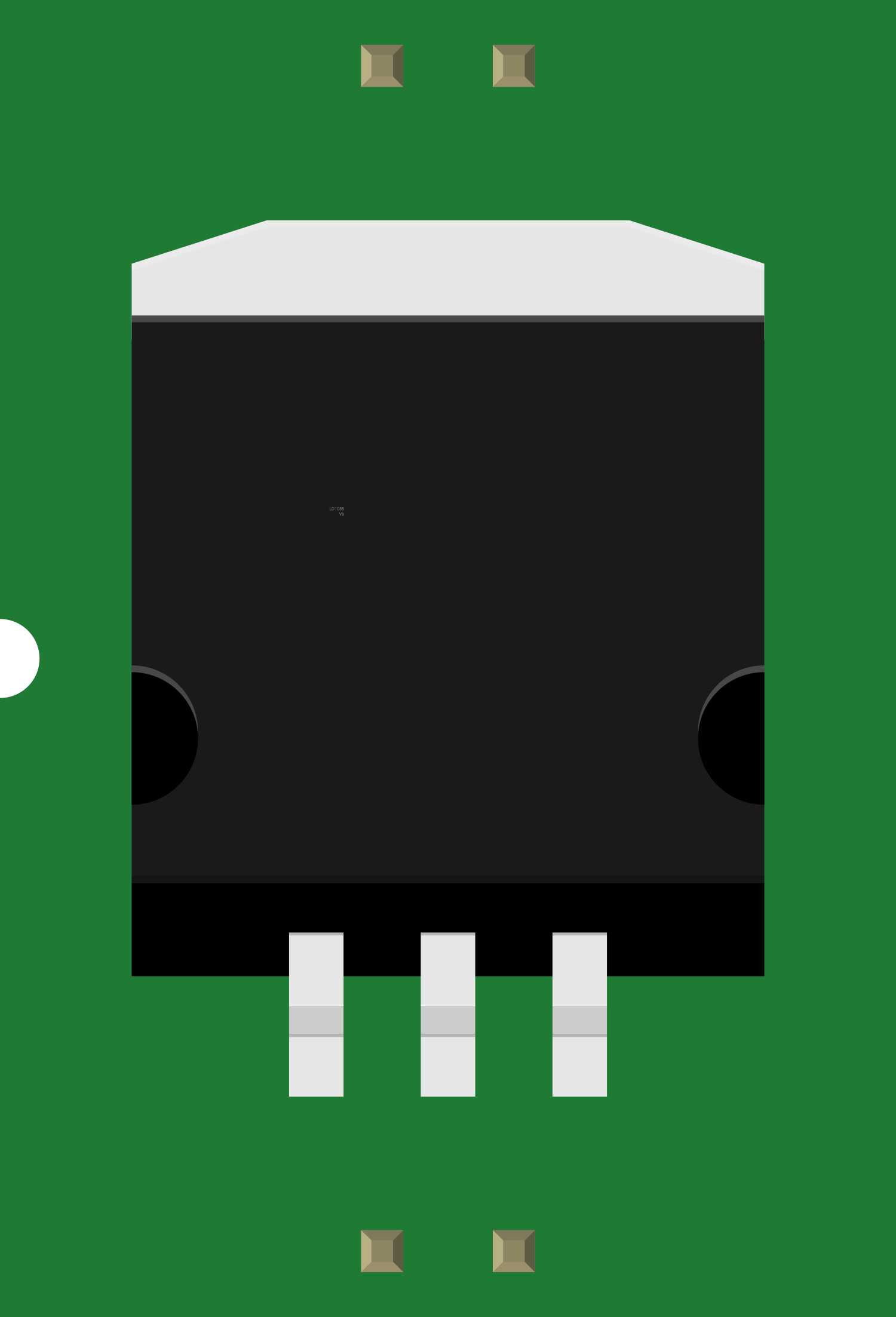
The V_REG_LD1085 is a versatile, low-dropout (LDO) linear voltage regulator capable of providing up to 3A of output current. With its ability to maintain a stable output voltage over a wide range of input voltages and load conditions, the LD1085 is ideal for powering sensitive electronic circuits. Common applications include microcontroller systems, portable devices, and other electronics requiring a stable power supply.
Explore Projects Built with V_REG_LD1085


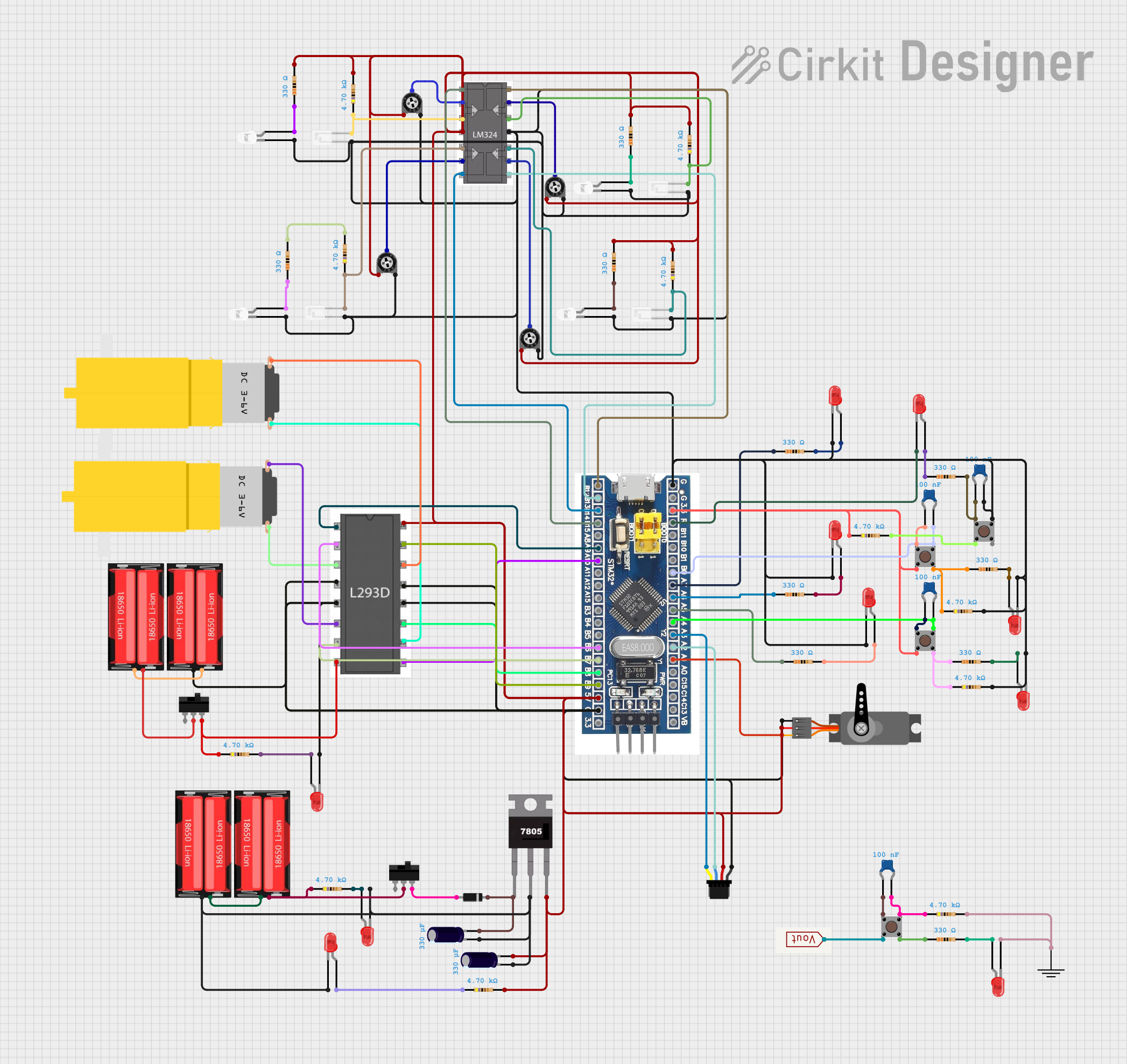
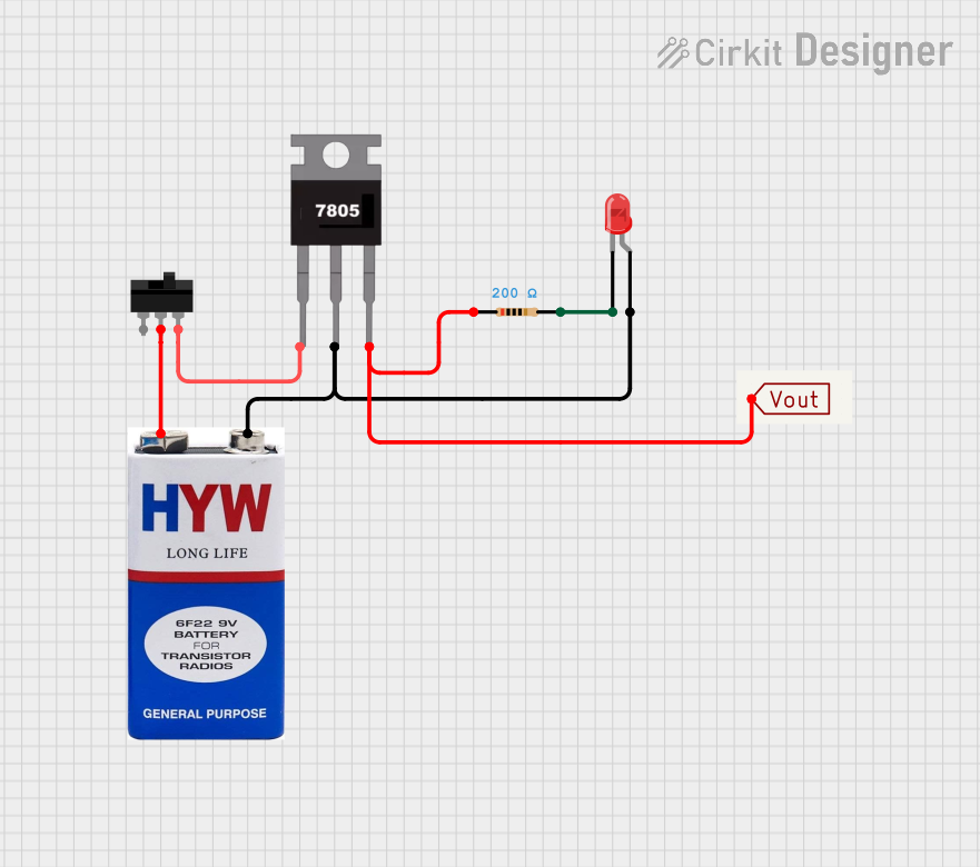
Explore Projects Built with V_REG_LD1085
Technical Specifications
Key Features
- Output Current: Up to 3A
- Dropout Voltage: Typically 1.3V at 3A load
- Adjustable Output Voltage: From 1.25V to adjustable
- Fixed Output Voltage Versions: 1.8V, 2.5V, 3.3V, 5V
- Overcurrent and Overtemperature Protection
- Low Ground Current
Pin Configuration and Descriptions
| Pin Number | Name | Description |
|---|---|---|
| 1 | ADJ/GND | Ground pin for fixed voltage versions or adjustment pin for variable output voltage |
| 2 | OUT | Regulated output voltage |
| 3 | IN | Input voltage |
Usage Instructions
Basic Connection
To use the V_REG_LD1085 in a circuit:
- Connect the IN pin to your unregulated input voltage source.
- Connect the OUT pin to your load.
- For fixed voltage versions, connect the ADJ/GND pin to the ground. For adjustable versions, connect a resistor network to the ADJ pin to set the desired output voltage.
Setting Output Voltage (Adjustable Version)
For the adjustable version, the output voltage can be set using two resistors (R1 and R2) as follows:
Vout = 1.25V * (1 + R2/R1) + Iadj * R2
Where Iadj is the adjustment pin current and is typically negligible.
Heat Dissipation
The LD1085 can dissipate significant heat when delivering high currents. Ensure adequate heat sinking is provided.
Capacitor Selection
For stability, the LD1085 requires output and input capacitors. A minimum of 10µF tantalum or 22µF aluminum electrolytic capacitor on the output is recommended. The input capacitor should be at least 10µF.
Example Circuit with Arduino UNO
// Example code for using the V_REG_LD1085 with an Arduino UNO
// This example assumes you are using the fixed 5V version of the LD1085.

void setup() {
  // Initialize the digital pin as an output.
  pinMode(LED_BUILTIN, OUTPUT);
}

void loop() {
  // Turn the LED on (HIGH is the voltage level)
  digitalWrite(LED_BUILTIN, HIGH);
  // Wait for a second
  delay(1000);
  // Turn the LED off by making the voltage LOW
  digitalWrite(LED_BUILTIN, LOW);
   // Wait for a second
  delay(1000);
}

// Note: Connect the LD1085 as follows:
// IN pin to an unregulated voltage source (6.3V to 15V)
// OUT pin to the 5V pin on the Arduino UNO
// ADJ/GND pin to the ground
Troubleshooting and FAQs
Common Issues
- Voltage Drop Under Load: Ensure the input voltage is sufficiently above the desired output voltage, considering the dropout voltage.
- Overheating: Check for adequate heat sinking and airflow around the regulator.
- Output Voltage Fluctuation: Verify the output and input capacitors are correctly rated and in good condition.
FAQs
Q: Can I use the LD1085 without a heat sink? A: It depends on the output current and the voltage drop across the regulator. For low currents and small voltage drops, a heat sink may not be necessary. However, for higher currents or voltage drops, a heat sink is recommended to prevent overheating.
Q: What is the maximum input voltage for the LD1085? A: The maximum input voltage is typically 30V, but always consult the datasheet for your specific version to confirm.
Q: How do I choose the right capacitors for stability? A: Use a minimum of 10µF tantalum or 22µF aluminum electrolytic capacitor on the output. The input capacitor should be at least 10µF. Larger values and low ESR capacitors can improve stability.
Q: What happens if the LD1085 gets too hot? A: The LD1085 has built-in thermal protection and will shut down if the internal temperature exceeds safe limits. Once it cools down, it will restart automatically.
For further assistance, always refer to the manufacturer's datasheet and application notes.