How to Use 1.44" TFT Display: Examples, Pinouts, and Specs
Introduction
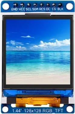
The 1.44-inch thin-film transistor (TFT) display is a compact, high-resolution screen that delivers vibrant and colorful visual output. It is widely used in embedded systems, portable devices, and DIY electronics projects for creating user interfaces, displaying graphical data, or showing images and text. Its small size and excellent color reproduction make it ideal for applications where space is limited but visual clarity is essential.
Explore Projects Built with 1.44" TFT Display


Explore Projects Built with 1.44" TFT Display
Common Applications:
- User interfaces for embedded systems
- Portable devices such as handheld meters or controllers
- Graphical data representation (e.g., charts, gauges)
- DIY electronics projects and Arduino-based systems
- Displaying images, animations, or text in compact devices
Technical Specifications
Below are the key technical details and pin configuration for the 1.44" TFT display:
Key Technical Details:
| Parameter | Specification |
|---|---|
| Display Type | TFT (Thin-Film Transistor) |
| Screen Size | 1.44 inches |
| Resolution | 128 x 128 pixels |
| Color Depth | 65K colors (16-bit RGB) |
| Interface | SPI (Serial Peripheral Interface) |
| Operating Voltage | 3.3V (logic level) |
| Backlight Voltage | 3.3V to 5V |
| Current Consumption | ~20mA (varies with backlight settings) |
| Driver IC | ST7735 |
| Viewing Angle | ~160° |
Pin Configuration:
| Pin Name | Pin Number | Description |
|---|---|---|
| VCC | 1 | Power supply input (3.3V or 5V) |
| GND | 2 | Ground |
| SCL | 3 | Serial Clock Line (SPI clock) |
| SDA | 4 | Serial Data Line (SPI data) |
| RES | 5 | Reset pin (active low) |
| DC | 6 | Data/Command control pin |
| CS | 7 | Chip Select (active low) |
| BL | 8 | Backlight control (optional, active high) |
Usage Instructions
How to Use the 1.44" TFT Display in a Circuit:
- Power Supply: Connect the
VCCpin to a 3.3V or 5V power source and theGNDpin to ground. - SPI Communication: Connect the
SCL(clock) andSDA(data) pins to the corresponding SPI pins on your microcontroller. - Control Pins:
- Connect the
RESpin to a GPIO pin on your microcontroller for resetting the display. - Use the
DCpin to toggle between data and command modes. - Connect the
CSpin to a GPIO pin to enable or disable the display.
- Connect the
- Backlight: Optionally, connect the
BLpin to a GPIO pin or directly to 3.3V/5V to control the backlight.
Important Considerations:
- Voltage Levels: Ensure that the logic voltage levels of your microcontroller match the display's requirements (3.3V). Use level shifters if necessary.
- SPI Speed: Configure the SPI clock speed appropriately (typically up to 15 MHz for the ST7735 driver).
- Initialization: The display requires proper initialization commands to function. Use a compatible library for your microcontroller to simplify this process.
Example Code for Arduino UNO:
Below is an example of how to use the 1.44" TFT display with an Arduino UNO using the Adafruit ST7735 library:
#include <Adafruit_GFX.h>    // Core graphics library
#include <Adafruit_ST7735.h> // Library for ST7735 driver
#include <SPI.h>             // SPI library

// Define pin connections
#define TFT_CS     10  // Chip Select pin
#define TFT_RST    9   // Reset pin
#define TFT_DC     8   // Data/Command pin

// Initialize the display object
Adafruit_ST7735 tft = Adafruit_ST7735(TFT_CS, TFT_DC, TFT_RST);

void setup() {
  // Initialize the serial monitor
  Serial.begin(9600);
  Serial.println("1.44\" TFT Display Test");

  // Initialize the display
  tft.initR(INITR_144GREENTAB); // Use the correct tab type for your display
  tft.fillScreen(ST77XX_BLACK); // Clear the screen with black color

  // Display a message
  tft.setTextColor(ST77XX_WHITE); // Set text color to white
  tft.setTextSize(1);             // Set text size
  tft.setCursor(0, 0);            // Set cursor position
  tft.println("Hello, World!");   // Print text to the display
}

void loop() {
  // Add your code here to update the display
}
Notes:
- Install the Adafruit GFX and Adafruit ST7735 libraries from the Arduino Library Manager before running the code.
- Adjust the
TFT_CS,TFT_RST, andTFT_DCpin definitions to match your wiring.
Troubleshooting and FAQs
Common Issues and Solutions:
Display Not Turning On:
- Verify the power connections (
VCCandGND). - Ensure the backlight pin (
BL) is connected or powered.
- Verify the power connections (
No Output on the Screen:
- Check the SPI connections (
SCL,SDA,CS,DC,RES). - Ensure the display is properly initialized in the code.
- Check the SPI connections (
Distorted or Incorrect Colors:
- Verify that the correct initialization commands are used for your display variant.
- Ensure the SPI clock speed is within the supported range.
Flickering or Unstable Display:
- Check for loose connections or poor soldering.
- Reduce the SPI clock speed if necessary.
FAQs:
Q: Can I use the display with a 5V microcontroller?
- A: Yes, but you may need level shifters for the SPI pins to avoid damaging the display.
Q: How do I control the backlight brightness?
- A: Use a PWM signal on the
BLpin to adjust the brightness.
- A: Use a PWM signal on the
Q: What is the maximum SPI clock speed supported?
- A: The ST7735 driver typically supports up to 15 MHz SPI clock speed.
By following this documentation, you can successfully integrate and use the 1.44" TFT display in your projects!