How to Use RTC DS1302: Examples, Pinouts, and Specs
Introduction
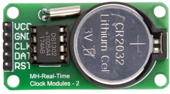
The DS1302 is a real-time clock (RTC) chip designed to keep track of the current time and date, including seconds, minutes, hours, day, date, month, and year. It communicates with microcontrollers via a simple serial interface and features a battery backup, allowing it to maintain accurate timekeeping even during power outages. Manufactured by Arduino with the part ID "UNO," the DS1302 is widely used in time-sensitive applications.
Explore Projects Built with RTC DS1302

Explore Projects Built with RTC DS1302
Common Applications and Use Cases
- Digital clocks and timers
- Data logging systems
- Home automation systems
- Alarm systems
- Scheduling and calendar-based applications
Technical Specifications
The DS1302 is a low-power RTC chip with the following key specifications:
| Parameter | Value |
|---|---|
| Operating Voltage | 2.0V to 5.5V |
| Operating Current | 300 µA (typical) |
| Backup Battery Voltage | 2.0V to 3.5V |
| Communication Protocol | Serial (3-wire interface) |
| Timekeeping Accuracy | ±2 ppm at 25°C |
| Clock Format | 24-hour or 12-hour with AM/PM indication |
| Temperature Range | -40°C to +85°C |
Pin Configuration and Descriptions
The DS1302 has an 8-pin configuration. Below is the pinout and description:
| Pin | Name | Description |
|---|---|---|
| 1 | VCC1 | Primary power supply (2.0V to 5.5V). |
| 2 | X1 | Oscillator input. Connect to a 32.768 kHz crystal. |
| 3 | X2 | Oscillator output. Connect to a 32.768 kHz crystal. |
| 4 | GND | Ground. |
| 5 | RST | Reset pin. Used to enable communication with the microcontroller. |
| 6 | I/O | Data input/output pin for serial communication. |
| 7 | SCLK | Serial clock input. Used to synchronize data transfer with the microcontroller. |
| 8 | VCC2 | Backup battery input (2.0V to 3.5V). |
Usage Instructions
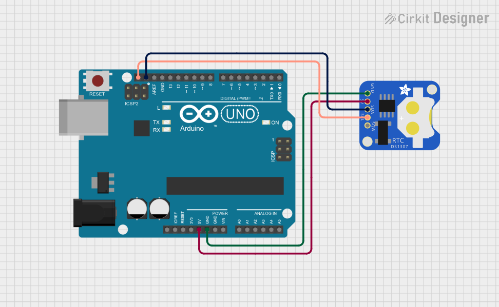
How to Use the DS1302 in a Circuit
- Power Supply: Connect the VCC1 pin to the primary power source (e.g., 5V from the Arduino UNO) and the GND pin to ground. Optionally, connect a backup battery to the VCC2 pin to maintain timekeeping during power loss.
- Crystal Oscillator: Attach a 32.768 kHz crystal between the X1 and X2 pins for accurate timekeeping.
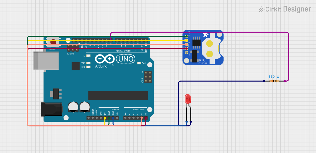
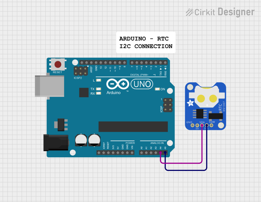
- Microcontroller Interface: Connect the RST, I/O, and SCLK pins to the Arduino UNO's digital pins for communication.
- Pull-Up Resistors: Use pull-up resistors (typically 10kΩ) on the I/O and RST lines to ensure proper signal levels.
Arduino UNO Example Code
Below is an example of how to interface the DS1302 with an Arduino UNO to read and set the time:
#include <DS1302.h> // Include the DS1302 library

// Define the DS1302 pins connected to the Arduino
#define RST_PIN 4   // Reset pin connected to Arduino digital pin 4
#define IO_PIN  5   // I/O pin connected to Arduino digital pin 5
#define SCLK_PIN 6  // Serial clock pin connected to Arduino digital pin 6

// Create a DS1302 object
DS1302 rtc(RST_PIN, IO_PIN, SCLK_PIN);

void setup() {
  Serial.begin(9600); // Initialize serial communication
  rtc.halt(false);    // Start the RTC
  rtc.writeProtect(false); // Disable write protection to allow time updates

  // Set the current time (Year, Month, Day, Hour, Minute, Second)
  rtc.setDOW(SUNDAY);       // Set Day of the Week
  rtc.setTime(12, 30, 0);   // Set time to 12:30:00
  rtc.setDate(15, 10, 2023); // Set date to October 15, 2023
}

void loop() {
  // Read and display the current time and date
  Serial.print("Time: ");
  Serial.print(rtc.getHour());
  Serial.print(":");
  Serial.print(rtc.getMinute());
  Serial.print(":");
  Serial.println(rtc.getSecond());

  Serial.print("Date: ");
  Serial.print(rtc.getDate());
  Serial.print("/");
  Serial.print(rtc.getMonth());
  Serial.print("/");
  Serial.println(rtc.getYear());

  delay(1000); // Wait for 1 second before updating
}
Important Considerations and Best Practices
- Backup Battery: Always connect a backup battery to the VCC2 pin to ensure uninterrupted timekeeping.
- Crystal Oscillator: Use a high-quality 32.768 kHz crystal for accurate timekeeping.
- Pull-Up Resistors: Ensure proper pull-up resistors are used on the I/O and RST lines to avoid communication errors.
- Write Protection: Enable write protection after setting the time to prevent accidental changes.
Troubleshooting and FAQs
Common Issues and Solutions
RTC Not Keeping Time
- Ensure the crystal oscillator is properly connected to the X1 and X2 pins.
- Verify that the backup battery is functional and connected to the VCC2 pin.
Communication Errors
- Check the connections between the DS1302 and the Arduino UNO.
- Ensure the RST, I/O, and SCLK pins are correctly assigned in the code.
Incorrect Time or Date
- Verify that the time and date are set correctly in the code.
- Check for power interruptions that may have reset the RTC.
FAQs
Q: Can the DS1302 handle daylight saving time adjustments?
A: No, the DS1302 does not have built-in support for daylight saving time. Adjustments must be handled in the microcontroller code.
Q: What is the maximum year supported by the DS1302?
A: The DS1302 supports years from 1900 to 2099.
Q: Can I use the DS1302 without a backup battery?
A: Yes, but the RTC will lose timekeeping functionality during power outages.
Q: How accurate is the DS1302?
A: The DS1302 has an accuracy of ±2 ppm at 25°C, which translates to a drift of about 1 minute per month under normal conditions.