How to Use White Led 3W: Examples, Pinouts, and Specs
Introduction
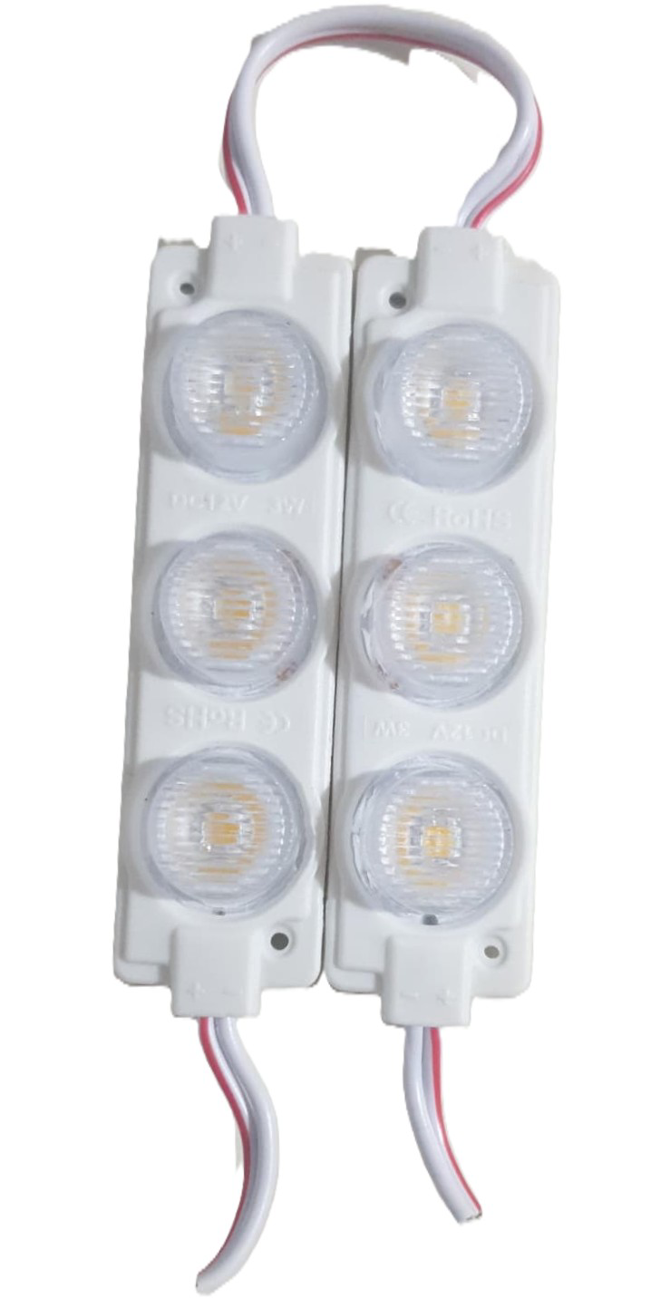
- The White LED 3W is a high-power light-emitting diode designed for illumination and lighting applications. It is known for its high brightness, energy efficiency, and long lifespan. This LED typically consumes 3 watts of power and emits bright white light, making it suitable for a wide range of uses.
- Common applications include:
- Flashlights and portable lighting devices
- Automotive lighting (e.g., headlights, interior lights)
- Architectural and decorative lighting
- DIY projects and hobbyist electronics
- Backlighting for displays and signage
Explore Projects Built with White Led 3W
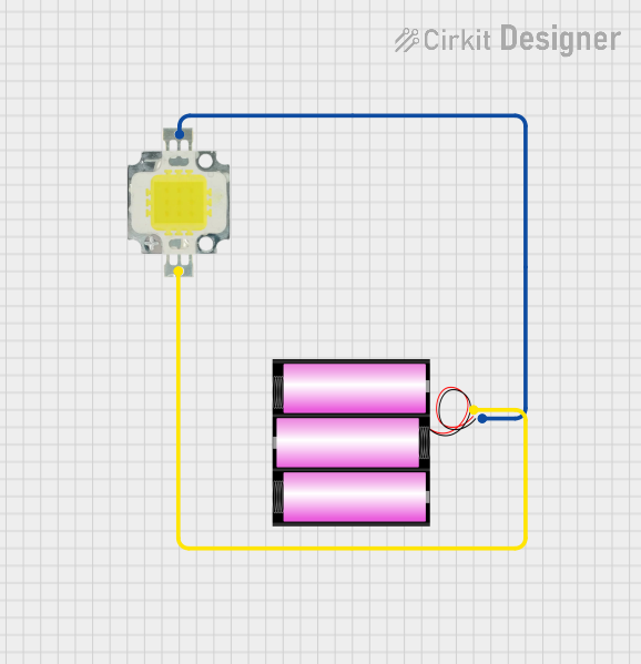
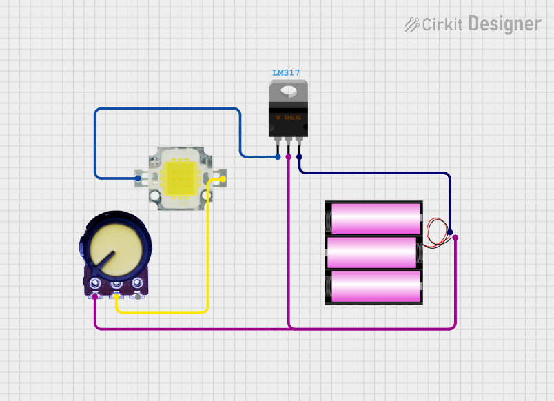
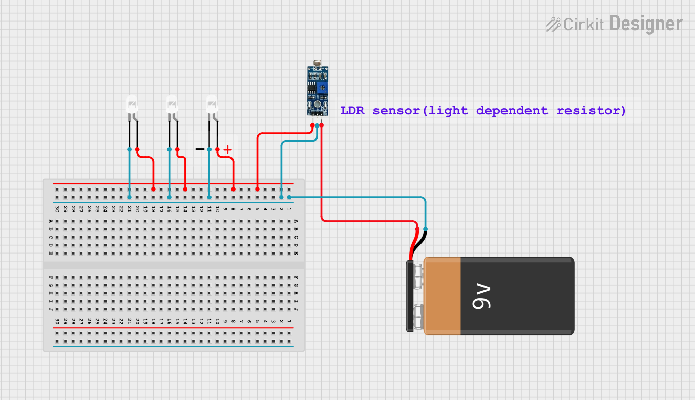
Explore Projects Built with White Led 3W
Technical Specifications
- Power Consumption: 3W
- Forward Voltage: 3.0V to 3.6V
- Forward Current: 700mA (typical)
- Luminous Flux: 200-300 lumens (depending on the model)
- Color Temperature: 6000K to 6500K (cool white)
- Viewing Angle: 120° (typical)
- Thermal Resistance: ≤10°C/W
- Operating Temperature: -40°C to +85°C
- Lifespan: >50,000 hours (under optimal conditions)
Pin Configuration and Descriptions
The White LED 3W typically has two terminals: Anode and Cathode. These are usually soldered onto a star-shaped aluminum PCB for heat dissipation.
| Pin Name | Description | Symbol |
|---|---|---|
| Anode | Positive terminal (connect to +V) | (+) |
| Cathode | Negative terminal (connect to GND) | (-) |
Usage Instructions
How to Use the White LED 3W in a Circuit
- Power Supply: Use a constant current LED driver or a current-limiting resistor to prevent overdriving the LED. The forward current should not exceed 700mA.
- Heat Dissipation: The LED generates significant heat during operation. Mount it on a heatsink or use thermal paste to ensure proper heat dissipation.
- Polarity: Ensure correct polarity when connecting the LED. The longer lead (if present) is the anode (+), and the shorter lead is the cathode (-).
- Wiring Example:
- Connect the anode to the positive terminal of the power supply through a current-limiting resistor or driver.
- Connect the cathode directly to the ground.
Example Circuit with Arduino UNO
The White LED 3W can be controlled using an Arduino UNO with a MOSFET for current handling. Below is an example circuit and code:
Circuit Diagram
- Components Required:
- White LED 3W
- N-channel MOSFET (e.g., IRF540N)
- 10kΩ resistor (pull-down for MOSFET gate)
- 220Ω resistor (current-limiting for Arduino pin)
- External power supply (e.g., 12V, 1A)
- Arduino UNO
Arduino Code
// Define the MOSFET gate pin connected to the Arduino
const int ledPin = 9; // PWM pin to control brightness

void setup() {
  pinMode(ledPin, OUTPUT); // Set the pin as output
}

void loop() {
  // Gradually increase brightness
  for (int brightness = 0; brightness <= 255; brightness++) {
    analogWrite(ledPin, brightness); // Set PWM duty cycle
    delay(10); // Small delay for smooth transition
  }

  // Gradually decrease brightness
  for (int brightness = 255; brightness >= 0; brightness--) {
    analogWrite(ledPin, brightness); // Set PWM duty cycle
    delay(10); // Small delay for smooth transition
  }
}
Important Considerations and Best Practices
- Current Limiting: Always use a constant current driver or a resistor to limit the current through the LED. Overdriving the LED can cause permanent damage.
- Heat Management: Ensure proper heat dissipation using a heatsink or thermal adhesive. Operating the LED without adequate cooling can significantly reduce its lifespan.
- Voltage Source: Use a power supply that matches the forward voltage range of the LED (3.0V to 3.6V). Avoid connecting the LED directly to a higher voltage source.
Troubleshooting and FAQs
Common Issues
LED Does Not Light Up:
- Check the polarity of the connections. Reverse polarity will prevent the LED from lighting up.
- Verify that the power supply provides sufficient voltage and current.
- Inspect the circuit for loose connections or damaged components.
LED Flickers:
- Ensure the power supply is stable and capable of delivering the required current.
- Check for poor solder joints or loose connections.
LED Overheats:
- Verify that a heatsink or thermal paste is properly installed.
- Ensure the current through the LED does not exceed 700mA.
LED Burns Out Quickly:
- Confirm that the forward voltage and current ratings are not being exceeded.
- Use a constant current driver to prevent overdriving the LED.
FAQs
Q: Can I connect the White LED 3W directly to a 5V or 12V power supply?
A: No, you must use a current-limiting resistor or a constant current driver to prevent overdriving the LED.
Q: How do I calculate the value of the current-limiting resistor?
A: Use Ohm's Law: ( R = \frac{V_{supply} - V_{forward}}{I_{forward}} ). For example, with a 12V supply, 3.2V forward voltage, and 700mA current:
( R = \frac{12 - 3.2}{0.7} = 12.57 , \Omega ). Use the nearest standard resistor value (e.g., 12Ω).
Q: Can I dim the White LED 3W?
A: Yes, you can dim the LED using PWM (Pulse Width Modulation) from a microcontroller like Arduino or a compatible LED driver.
Q: What happens if I exceed the maximum current rating?
A: Exceeding the current rating can cause the LED to overheat, degrade, or fail permanently.
By following these guidelines and best practices, you can effectively use the White LED 3W in your projects and applications.