Cirkit Designer Logo
Cirkit Designer
Your all-in-one circuit design IDE
Home / 
Component Documentation

How to Use MX1508: Examples, Pinouts, and Specs

Image of MX1508
Cirkit Designer LogoDesign with MX1508 in Cirkit Designer

Introduction

The MX1508 is a dual operational amplifier (op-amp) designed for low-power applications. It features high gain, low noise, and excellent stability, making it ideal for signal conditioning, amplification, and other analog signal processing tasks. Its compact design and efficient performance make it a popular choice in audio systems, sensor signal amplification, and precision measurement circuits.

Explore Projects Built with MX1508

Use Cirkit Designer to design, explore, and prototype these projects online. Some projects support real-time simulation. Click "Open Project" to start designing instantly!
WiFi-Controlled Basket-Carrying Robot with GPS and GSM Notification
Image of trash collecting vessel: A project utilizing MX1508 in a practical application
This circuit is designed for a 4-wheeled WiFi-controlled car with a basket, which uses an ESP8266 NodeMCU microcontroller for logic control. It features an IR sensor for basket full detection, a GPS module for location tracking, and a GSM module (Sim800l) for sending SMS notifications. The L298N motor driver controls four DC gearmotors for movement, and the system is powered by a Li-ion battery with a 7805 voltage regulator providing stable power to the GSM module.
Cirkit Designer LogoOpen Project in Cirkit Designer
ESP32C3-Based Multi-Sensor Data Logger with Wi-Fi and SD Card Storage
Image of Petora_v1: A project utilizing MX1508 in a practical application
This circuit is a data logging and transmission system that collects environmental and positional data from various sensors (BME/BMP280, HMC5883L, MAX30102, GPS NEO 6M) and records it to an SD card. The data is also sent over WiFi to a specified server using an ESP32 microcontroller.
Cirkit Designer LogoOpen Project in Cirkit Designer
Arduino Mega 2560 Based Security System with Fingerprint Authentication and SMS Alerts
Image of Door security system: A project utilizing MX1508 in a practical application
This circuit features an Arduino Mega 2560 microcontroller interfaced with a SIM800L GSM module, two fingerprint scanners, an I2C LCD display, an IR sensor, and a piezo buzzer. Power management is handled by a PowerBoost 1000 Basic Pad USB, a TP4056 charging module, and a Li-ion 18650 battery, with an option to use a Mini AC-DC 110V-230V to 5V 700mA module for direct power supply. The primary functionality appears to be a security system with GSM communication capabilities, biometric access control, and visual/audible feedback.
Cirkit Designer LogoOpen Project in Cirkit Designer
ESP32-Controlled Traffic Light and Multi-Motor Driver System
Image of Projeto final: A project utilizing MX1508 in a practical application
This circuit features an ESP32 microcontroller connected to a traffic light module and multiple DC motors via two L298N motor drivers. The ESP32 controls the traffic light states and motor operations, likely for a model intersection with moving parts. The circuit also includes MT3608 boost converters to step up the voltage from a 4 x AAA battery mount to the required levels for the motor drivers, and an MG996R servo motor controlled directly by the ESP32.
Cirkit Designer LogoOpen Project in Cirkit Designer

Explore Projects Built with MX1508

Use Cirkit Designer to design, explore, and prototype these projects online. Some projects support real-time simulation. Click "Open Project" to start designing instantly!
Image of trash collecting vessel: A project utilizing MX1508 in a practical application
WiFi-Controlled Basket-Carrying Robot with GPS and GSM Notification
This circuit is designed for a 4-wheeled WiFi-controlled car with a basket, which uses an ESP8266 NodeMCU microcontroller for logic control. It features an IR sensor for basket full detection, a GPS module for location tracking, and a GSM module (Sim800l) for sending SMS notifications. The L298N motor driver controls four DC gearmotors for movement, and the system is powered by a Li-ion battery with a 7805 voltage regulator providing stable power to the GSM module.
Cirkit Designer LogoOpen Project in Cirkit Designer
Image of Petora_v1: A project utilizing MX1508 in a practical application
ESP32C3-Based Multi-Sensor Data Logger with Wi-Fi and SD Card Storage
This circuit is a data logging and transmission system that collects environmental and positional data from various sensors (BME/BMP280, HMC5883L, MAX30102, GPS NEO 6M) and records it to an SD card. The data is also sent over WiFi to a specified server using an ESP32 microcontroller.
Cirkit Designer LogoOpen Project in Cirkit Designer
Image of Door security system: A project utilizing MX1508 in a practical application
Arduino Mega 2560 Based Security System with Fingerprint Authentication and SMS Alerts
This circuit features an Arduino Mega 2560 microcontroller interfaced with a SIM800L GSM module, two fingerprint scanners, an I2C LCD display, an IR sensor, and a piezo buzzer. Power management is handled by a PowerBoost 1000 Basic Pad USB, a TP4056 charging module, and a Li-ion 18650 battery, with an option to use a Mini AC-DC 110V-230V to 5V 700mA module for direct power supply. The primary functionality appears to be a security system with GSM communication capabilities, biometric access control, and visual/audible feedback.
Cirkit Designer LogoOpen Project in Cirkit Designer
Image of Projeto final: A project utilizing MX1508 in a practical application
ESP32-Controlled Traffic Light and Multi-Motor Driver System
This circuit features an ESP32 microcontroller connected to a traffic light module and multiple DC motors via two L298N motor drivers. The ESP32 controls the traffic light states and motor operations, likely for a model intersection with moving parts. The circuit also includes MT3608 boost converters to step up the voltage from a 4 x AAA battery mount to the required levels for the motor drivers, and an MG996R servo motor controlled directly by the ESP32.
Cirkit Designer LogoOpen Project in Cirkit Designer

Common Applications

  • Audio preamplifiers and filters
  • Sensor signal conditioning
  • Analog-to-digital converter (ADC) input buffering
  • Precision measurement and instrumentation
  • Low-power portable devices

Technical Specifications

Key Technical Details

Parameter Value
Supply Voltage Range 3V to 15V (single supply)
Input Offset Voltage ≤ 5 mV
Input Bias Current ≤ 250 nA
Gain Bandwidth Product 1 MHz
Slew Rate 0.5 V/µs
Output Voltage Swing 0V to (Vcc - 1.5V)
Operating Temperature -40°C to +85°C
Package Type SOP-8, DIP-8

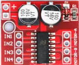
Pin Configuration and Descriptions

The MX1508 is typically available in an 8-pin package. Below is the pinout and description:

Pin Number Pin Name Description
1 OUT1 Output of Op-Amp 1
2 IN1- Inverting Input of Op-Amp 1
3 IN1+ Non-Inverting Input of Op-Amp 1
4 VSS/GND Ground (negative power supply)
5 IN2+ Non-Inverting Input of Op-Amp 2
6 IN2- Inverting Input of Op-Amp 2
7 OUT2 Output of Op-Amp 2
8 VDD Positive Power Supply

Usage Instructions

How to Use the MX1508 in a Circuit

  1. Power Supply: Connect the VDD pin to a positive voltage source (3V to 15V) and the VSS pin to ground.
  2. Input Configuration:
    • For single-ended input, connect the signal to the non-inverting input (IN+), and ground the inverting input (IN-).
    • For differential input, connect the two input signals to IN+ and IN-.
  3. Output: The amplified signal will be available at the OUT pin. Ensure the load impedance is compatible with the op-amp's output drive capability.
  4. Feedback Network: Use resistors and/or capacitors in the feedback loop to set the desired gain and frequency response.
  5. Bypass Capacitors: Place decoupling capacitors (e.g., 0.1 µF ceramic) close to the power supply pins to reduce noise.

Important Considerations and Best Practices

  • Avoid exceeding the maximum supply voltage to prevent damage to the component.
  • Use proper grounding techniques to minimize noise and interference.
  • For high-frequency applications, consider adding a small capacitor in parallel with the feedback resistor to improve stability.
  • Ensure the input signal does not exceed the common-mode voltage range of the op-amp.

Example: Connecting the MX1508 to an Arduino UNO

The MX1508 can be used to amplify an analog signal before feeding it into the Arduino's ADC. Below is an example circuit and code:

Circuit Description

  • Connect the MX1508's VDD to the Arduino's 5V pin and VSS to GND.
  • Connect the signal source to IN1+ and ground IN1-.
  • Connect OUT1 to an analog input pin on the Arduino (e.g., A0).

Arduino Code Example

// Example code to read an amplified signal from the MX1508 using Arduino UNO

const int analogPin = A0; // Pin connected to MX1508 OUT1
int signalValue = 0;      // Variable to store the analog reading

void setup() {
  Serial.begin(9600); // Initialize serial communication at 9600 baud
}

void loop() {
  signalValue = analogRead(analogPin); // Read the amplified signal
  Serial.print("Amplified Signal Value: ");
  Serial.println(signalValue); // Print the value to the Serial Monitor
  delay(500); // Wait for 500ms before the next reading
}

Troubleshooting and FAQs

Common Issues and Solutions

  1. No Output Signal:

    • Ensure the power supply is connected and within the specified range.
    • Verify the input signal is properly connected and within the op-amp's input range.
    • Check the feedback network for proper configuration.
  2. Output Signal is Distorted:

    • Verify that the load impedance is not too low for the op-amp to drive.
    • Check for excessive input signal levels that may cause clipping.
    • Add bypass capacitors to the power supply pins to reduce noise.
  3. Oscillations or Instability:

    • Add a small capacitor (e.g., 10 pF) in parallel with the feedback resistor.
    • Ensure proper grounding and minimize long, unshielded signal wires.

FAQs

Q: Can the MX1508 operate with a single power supply?
A: Yes, the MX1508 is designed to operate with a single supply voltage. Ensure the input signal is within the common-mode voltage range.

Q: What is the maximum gain I can achieve with the MX1508?
A: The maximum gain depends on the feedback network configuration. However, for high gains, ensure stability by adding compensation capacitors if needed.

Q: Can I use the MX1508 for audio applications?
A: Yes, the MX1508's low noise and high gain make it suitable for audio preamplifiers and filters.