How to Use MOSFET 4 kanal: Examples, Pinouts, and Specs
Introduction
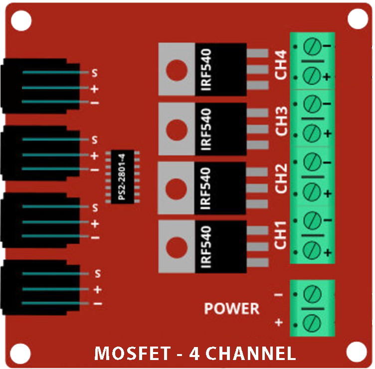
The MOSFET 4 Kanal (IRF9540N), manufactured by Basti, is a Metal-Oxide-Semiconductor Field-Effect Transistor designed for switching and amplifying electronic signals. This component features four independent channels, making it ideal for applications requiring multiple switching operations in a compact form factor. With its high efficiency and fast switching capabilities, the IRF9540N is widely used in power management, motor control, LED drivers, and audio amplifiers.
Explore Projects Built with MOSFET 4 kanal
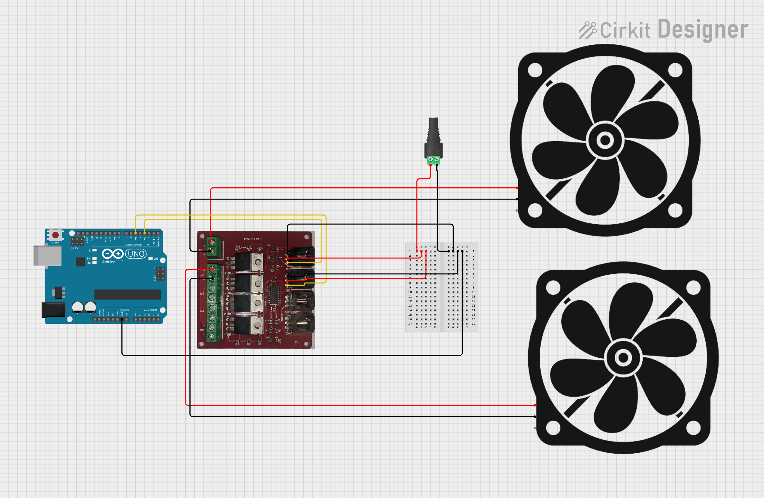


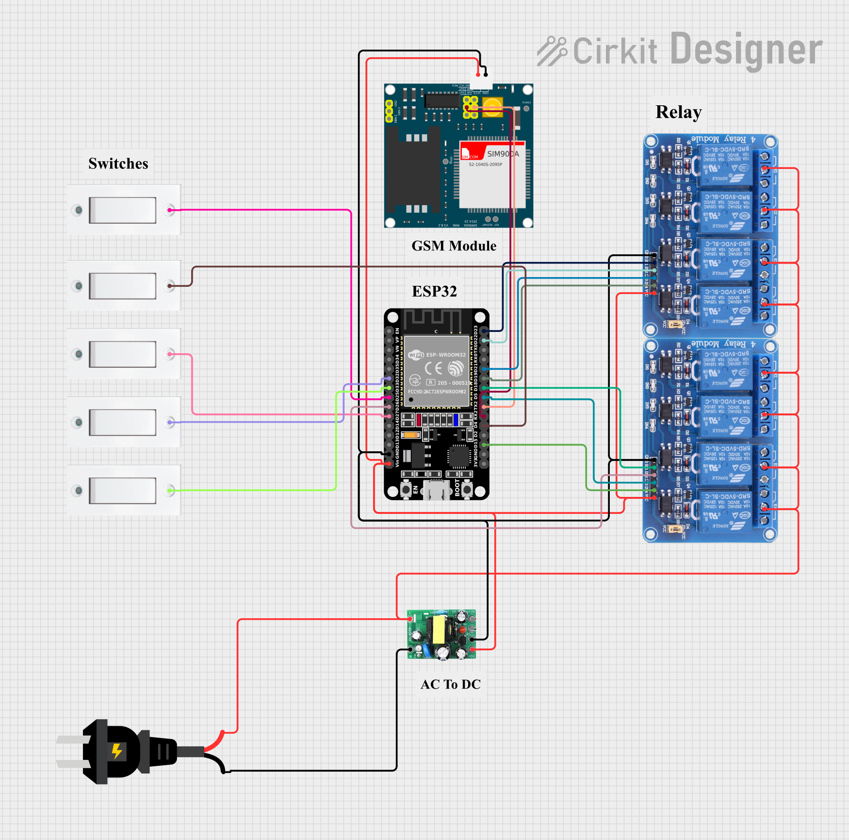
Explore Projects Built with MOSFET 4 kanal
Common Applications
- DC motor control in robotics and automation
- LED dimming and lighting systems
- Power supply regulation and conversion
- Audio signal amplification
- High-speed switching in digital circuits
Technical Specifications
Key Specifications
| Parameter | Value |
|---|---|
| Manufacturer | Basti |
| Part Number | IRF9540N |
| Type | P-Channel MOSFET |
| Number of Channels | 4 |
| Maximum Drain-Source Voltage (VDS) | -100 V |
| Maximum Gate-Source Voltage (VGS) | ±20 V |
| Continuous Drain Current (ID) | -23 A |
| Power Dissipation (PD) | 200 W |
| RDS(on) (On-Resistance) | 0.117 Ω |
| Operating Temperature Range | -55°C to +175°C |
| Package Type | TO-220 |
Pin Configuration
The IRF9540N MOSFET is typically housed in a TO-220 package. Below is the pin configuration for each channel:
| Pin Number | Pin Name | Description |
|---|---|---|
| 1 | Gate (G) | Controls the MOSFET switching operation |
| 2 | Drain (D) | Current flows out of this terminal |
| 3 | Source (S) | Current flows into this terminal |
Usage Instructions
How to Use the MOSFET 4 Kanal in a Circuit
- Power Supply: Ensure the power supply voltage does not exceed the maximum VDS (-100 V) or VGS (±20 V) ratings.
- Gate Resistor: Use a gate resistor (typically 10–100 Ω) to limit the inrush current to the gate and prevent damage.
- Load Connection: Connect the load (e.g., motor, LED) between the drain and the positive supply voltage for a P-Channel MOSFET.
- Gate Control: Apply a voltage lower than the source voltage to the gate to turn the MOSFET on. For example, if the source is at 12 V, applying 0 V to the gate will turn the MOSFET on.
- Heat Dissipation: Use a heatsink if the MOSFET is expected to dissipate significant power.
Example Circuit with Arduino UNO
Below is an example of using the IRF9540N MOSFET to control an LED with an Arduino UNO:
Circuit Connections
- Source (S): Connect to the positive terminal of the power supply (e.g., 12 V).
- Drain (D): Connect to one terminal of the LED. The other terminal of the LED connects to ground via a current-limiting resistor.
- Gate (G): Connect to a PWM-capable pin on the Arduino (e.g., Pin 9) through a 100 Ω resistor.
Arduino Code
// Example code to control an LED using the IRF9540N MOSFET
// Pin 9 is used as the PWM output to control the MOSFET gate

const int mosfetGatePin = 9; // MOSFET gate connected to Arduino Pin 9

void setup() {
  pinMode(mosfetGatePin, OUTPUT); // Set the gate pin as an output
}

void loop() {
  analogWrite(mosfetGatePin, 128); // Set PWM duty cycle to 50% (LED dimmed)
  delay(1000);                     // Wait for 1 second
  analogWrite(mosfetGatePin, 255); // Set PWM duty cycle to 100% (LED fully on)
  delay(1000);                     // Wait for 1 second
}
Best Practices
- Always check the polarity of the connections to avoid damaging the MOSFET.
- Use a flyback diode across inductive loads (e.g., motors) to protect the MOSFET from voltage spikes.
- Avoid exceeding the maximum ratings for voltage, current, and power dissipation.
Troubleshooting and FAQs
Common Issues and Solutions
MOSFET Not Switching Properly
- Cause: Insufficient gate voltage.
- Solution: Ensure the gate voltage is at least 10 V lower than the source voltage for proper switching.
Excessive Heat Generation
- Cause: High current or inadequate cooling.
- Solution: Use a heatsink or reduce the load current.
MOSFET Fails to Turn Off
- Cause: Gate voltage not fully returning to the source voltage.
- Solution: Add a pull-up resistor (e.g., 10 kΩ) between the gate and source.
Load Not Operating
- Cause: Incorrect wiring or damaged MOSFET.
- Solution: Double-check the circuit connections and replace the MOSFET if necessary.
FAQs
Q1: Can I use the IRF9540N for high-frequency switching?
A1: Yes, the IRF9540N supports high-speed switching, but ensure proper gate drive circuitry to minimize switching losses.
Q2: Is the IRF9540N suitable for low-voltage applications?
A2: While it can be used in low-voltage circuits, its on-resistance (RDS(on)) may result in higher power losses compared to MOSFETs optimized for low-voltage operation.
Q3: Can I use the IRF9540N with a 3.3 V microcontroller?
A3: No, the IRF9540N requires a higher gate voltage for proper operation. Use a level shifter or a MOSFET driver circuit.
By following this documentation, users can effectively integrate the IRF9540N MOSFET 4 Kanal into their projects for reliable and efficient performance.