
How to Use HMC1051Z: Examples, Pinouts, and Specs
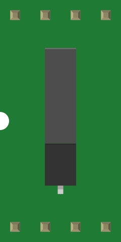
 Design with HMC1051Z in Cirkit Designer
Introduction
The HMC1051Z, manufactured by Honeywell, is a high-performance RF switch designed for applications in the frequency range of DC to 6 GHz. This component is known for its low insertion loss, high isolation, and fast switching speeds, making it an ideal choice for a wide range of RF and microwave systems. Its robust design ensures reliable performance in demanding environments, making it suitable for both commercial and industrial applications.
Explore Projects Built with HMC1051Z
 Open Project in Cirkit Designer
 Open Project in Cirkit Designer
 Open Project in Cirkit Designer
 Open Project in Cirkit Designer
Explore Projects Built with HMC1051Z
Open Project in Cirkit DesignerOpen Project in Cirkit DesignerOpen Project in Cirkit DesignerOpen Project in Cirkit DesignerCommon Applications and Use Cases
- Wireless communication systems
- RF signal routing in test and measurement equipment
- Satellite communication systems
- Radar systems
- Microwave radio links
- Antenna switching in multi-band systems
Technical Specifications
Key Technical Details
| Parameter | Value |
|---|---|
| Frequency Range | DC to 6 GHz |
| Insertion Loss | < 1 dB (typical) |
| Isolation | > 40 dB (typical) |
| Switching Speed | < 100 ns |
| Input Power Handling | Up to +30 dBm |
| Supply Voltage | +3.3 V to +5 V |
| Control Voltage Levels | 0 V (Low), 3.3 V or 5 V (High) |
| Operating Temperature | -40°C to +85°C |
| Package Type | Surface Mount (SOT-23-6) |
Pin Configuration and Descriptions
The HMC1051Z is housed in a SOT-23-6 package. The pinout and descriptions are as follows:
| Pin Number | Name | Description |
|---|---|---|
| 1 | RF1 | RF input/output port 1 |
| 2 | GND | Ground connection |
| 3 | VCTL | Control voltage input for switching |
| 4 | RF2 | RF input/output port 2 |
| 5 | GND | Ground connection |
| 6 | VDD | Supply voltage input (+3.3 V to +5 V) |
Usage Instructions
How to Use the HMC1051Z in a Circuit
- Power Supply: Connect the VDD pin to a regulated power supply of +3.3 V to +5 V. Ensure proper decoupling capacitors (e.g., 0.1 µF and 10 µF) are placed close to the pin to minimize noise.
- Control Voltage: Apply a control voltage to the VCTL pin to toggle the RF switch:
- 0 V (Low): Connects RF1 to RF2.
- 3.3 V or 5 V (High): Disconnects RF1 from RF2.
- RF Connections: Connect the RF signal paths to RF1 and RF2. Use 50-ohm impedance-matched traces for optimal performance.
- Grounding: Ensure all GND pins are connected to a low-impedance ground plane to minimize noise and improve isolation.
Important Considerations and Best Practices
- Impedance Matching: Use 50-ohm transmission lines for all RF connections to minimize signal reflections and losses.
- Thermal Management: Ensure adequate heat dissipation, especially in high-power applications.
- Control Signal Integrity: Use clean and noise-free control signals to avoid unintended switching.
- PCB Layout: Keep RF traces as short as possible and avoid sharp bends to reduce signal degradation.
Example: Connecting the HMC1051Z to an Arduino UNO
The HMC1051Z can be controlled using an Arduino UNO to toggle the RF switch. Below is an example circuit and code:
Circuit Connections
| HMC1051Z Pin | Arduino UNO Pin | Description |
|---|---|---|
| VDD | 5V | Power supply |
| GND | GND | Ground |
| VCTL | Digital Pin 7 | Control signal for switching |
Arduino Code
// Define the control pin for the HMC1051Z
const int controlPin = 7;

void setup() {
  // Set the control pin as an output
  pinMode(controlPin, OUTPUT);
}

void loop() {
  // Turn the RF switch ON (connect RF1 to RF2)
  digitalWrite(controlPin, LOW);
  delay(1000); // Wait for 1 second

  // Turn the RF switch OFF (disconnect RF1 from RF2)
  digitalWrite(controlPin, HIGH);
  delay(1000); // Wait for 1 second
}
Troubleshooting and FAQs
Common Issues and Solutions
No RF Signal Passing Through
- Cause: Incorrect control voltage applied to the VCTL pin.
- Solution: Verify the control voltage levels. Ensure 0 V for ON and 3.3 V/5 V for OFF.
High Insertion Loss
- Cause: Impedance mismatch in the RF signal path.
- Solution: Use 50-ohm impedance-matched traces and connectors.
Switching Delays
- Cause: Slow control signal transitions.
- Solution: Ensure the control signal has fast rise and fall times.
Overheating
- Cause: Excessive RF input power or poor thermal management.
- Solution: Ensure the input power does not exceed +30 dBm and provide adequate heat dissipation.
FAQs
Q1: Can the HMC1051Z operate at frequencies below 1 MHz?
Yes, the HMC1051Z supports a frequency range starting from DC, making it suitable for low-frequency applications.
Q2: What is the maximum control voltage for the VCTL pin?
The maximum control voltage is 5 V. Exceeding this value may damage the component.
Q3: Can I use the HMC1051Z in outdoor environments?
Yes, the HMC1051Z can operate in temperatures ranging from -40°C to +85°C, but ensure it is housed in a weatherproof enclosure for outdoor use.
Q4: How do I minimize crosstalk between RF1 and RF2?
Use proper grounding and maintain physical separation between RF traces to reduce crosstalk.
This concludes the documentation for the HMC1051Z. For further assistance, refer to the manufacturer's datasheet or contact Honeywell support.