How to Use 12V SINGLE CHANNEL RELAY: Examples, Pinouts, and Specs
Introduction
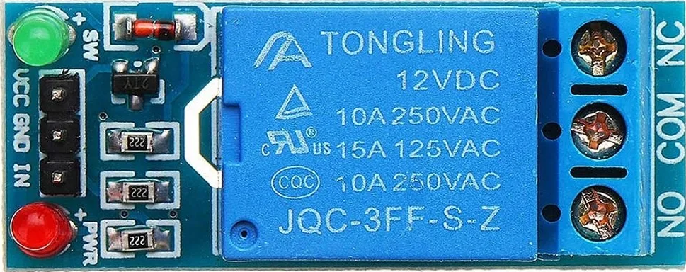
A 12V Single Channel Relay is an electronic switch that allows you to control a high power circuit with a low power signal. The relay module typically consists of a coil, a relay (electromechanical switch), input and output terminals, and a driving circuit. It is commonly used in applications where it is necessary to control a large power load with a small digital signal, such as home automation, industrial controls, and automotive electronics.
Explore Projects Built with 12V SINGLE CHANNEL RELAY

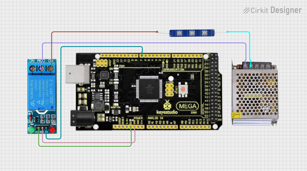
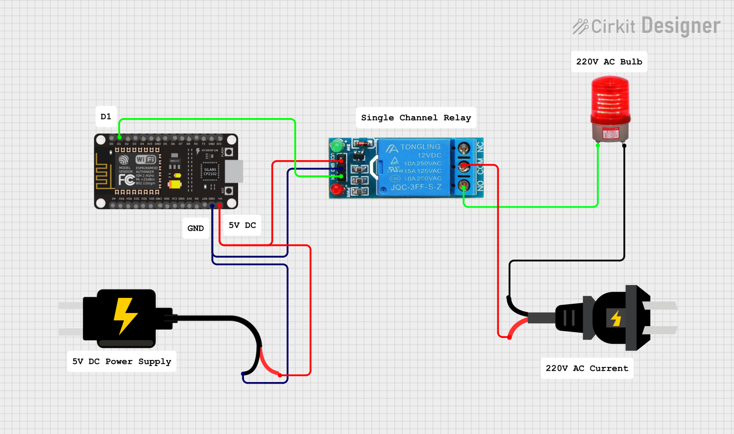
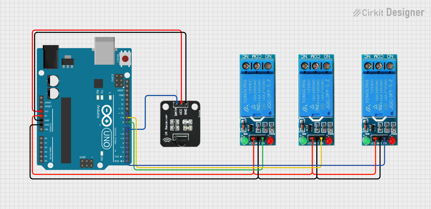
Explore Projects Built with 12V SINGLE CHANNEL RELAY
Technical Specifications
Key Technical Details
- Operating Voltage: 12V DC
- Coil Current: Approx. 30-50mA
- Contact Capacity: (Resistive load) 10A/250V AC or 10A/30V DC
- Switching Voltage: Max 250V AC / 30V DC
- Switching Current: Max 10A
- Operating Time: 10ms (Max)
- Release Time: 5ms (Max)
- Operating Temperature: -30°C to +85°C
Pin Configuration and Descriptions
| Pin | Description |
|---|---|
| VCC | Connect to 12V power supply |
| GND | Connect to ground |
| IN | Control signal input (active LOW) |
| NO | Normally open contact |
| COM | Common contact |
| NC | Normally closed contact |
Usage Instructions
How to Use the Component in a Circuit
Power Connections:
- Connect the VCC pin to a 12V power supply.
- Connect the GND pin to the ground of the power supply.
Control Signal:
- Connect the IN pin to a digital output of a microcontroller, such as an Arduino UNO.
Load Connections:
- Connect the device you want to control to the NO or NC and COM pins, depending on whether you want the device to be on when the relay is activated (NO) or off (NC).
Important Considerations and Best Practices
- Ensure that the power supply voltage matches the operating voltage of the relay.
- Do not exceed the maximum switching voltage and current ratings.
- Use a flyback diode across the relay coil to prevent back EMF when the coil is de-energized.
- Consider using a transistor to drive the relay if the control signal cannot provide sufficient current.
- Always ensure proper isolation between the low voltage control side and the high voltage load side.
Example Code for Arduino UNO
// Define the relay control pin
const int relayPin = 7;

void setup() {
  // Set the relay pin as an output
  pinMode(relayPin, OUTPUT);
  // Start with the relay off
  digitalWrite(relayPin, HIGH);
}

void loop() {
  // Turn on the relay
  digitalWrite(relayPin, LOW);
  delay(1000); // Wait for 1 second
  // Turn off the relay
  digitalWrite(relayPin, HIGH);
  delay(1000); // Wait for 1 second
}
Troubleshooting and FAQs
Common Issues
- Relay does not activate: Check the power supply and control signal connections. Ensure that the IN pin is receiving a LOW signal to activate the relay.
- Intermittent operation: Verify that the connections are secure and not loose. Also, check for any signs of overheating or damage to the relay.
- Noise issues: Relays can cause electrical noise; use snubber circuits or opto-isolation if necessary.
Solutions and Tips for Troubleshooting
- If the relay does not switch, ensure that the input signal is correctly toggled between HIGH and LOW states.
- Use a multimeter to check the continuity of the relay contacts in both NO and NC states.
- Ensure that the load does not exceed the rated capacity of the relay to prevent damage.
FAQs
Q: Can I use this relay with a 5V control signal? A: Yes, but ensure that the VCC is still connected to a 12V supply, and the control signal is compatible with the relay's input requirements.
Q: Is it necessary to use a flyback diode with this relay? A: Yes, it is recommended to use a flyback diode across the relay coil to protect the control circuitry from voltage spikes.
Q: Can I control this relay with a PWM signal? A: It is not recommended to use PWM to control a relay, as the relay may not function properly with rapidly changing signals. Use a steady HIGH or LOW signal instead.