How to Use IBT2 Motordriver: Examples, Pinouts, and Specs
Introduction
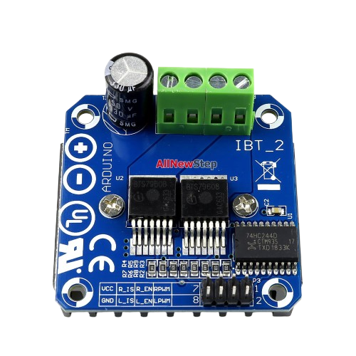
The IBT2 Motor Driver is a dual H-bridge motor driver designed to control DC motors and stepper motors. It enables bidirectional control of motors, allowing for both forward and reverse operation. With its ability to handle high current loads, the IBT2 is ideal for applications in robotics, automation, and other projects requiring precise motor control. Its robust design makes it suitable for driving large motors in demanding environments.
Explore Projects Built with IBT2 Motordriver


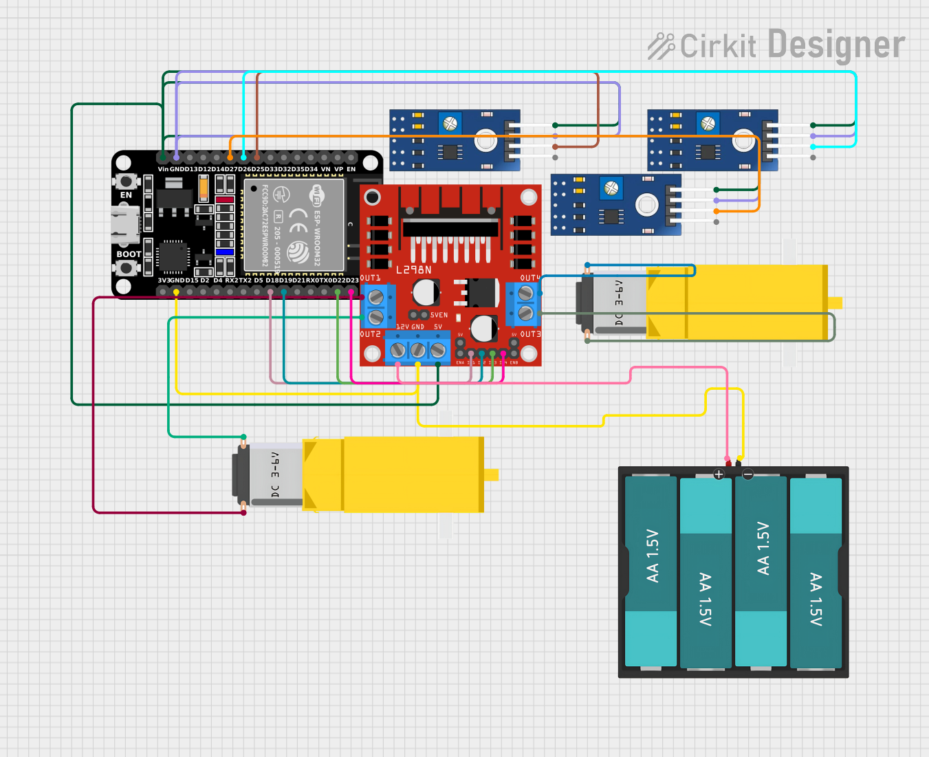
Explore Projects Built with IBT2 Motordriver
Common Applications
- Robotics (e.g., motorized arms, wheeled robots)
- Automation systems (e.g., conveyor belts, automated gates)
- Electric vehicles and carts
- CNC machines and 3D printers
- High-power motor control in industrial applications
Technical Specifications
The IBT2 Motor Driver is built to handle high-power motors with ease. Below are its key technical specifications:
| Parameter | Value |
|---|---|
| Operating Voltage | 6V to 27V |
| Continuous Current | 43A |
| Peak Current | 160A (short duration) |
| Control Voltage | 3.3V to 5V (logic level) |
| PWM Frequency | Up to 20 kHz |
| Dimensions | 55mm x 60mm x 30mm |
| Operating Temperature | -25°C to +80°C |
Pin Configuration and Descriptions
The IBT2 Motor Driver has a total of 8 pins for control and power connections. Below is the pinout and description:
| Pin Name | Type | Description |
|---|---|---|
| VCC | Power Input | Connect to the motor power supply (6V to 27V). |
| GND | Power Ground | Connect to the ground of the power supply. |
| INA | Logic Input | Input A for motor direction control. |
| INB | Logic Input | Input B for motor direction control. |
| PWM | Logic Input | Pulse Width Modulation input for speed control. |
| EN | Logic Input | Enable pin. Set HIGH to enable the motor driver. |
| OUT1 | Motor Output | Connect to one terminal of the motor. |
| OUT2 | Motor Output | Connect to the other terminal of the motor. |
Usage Instructions
How to Use the IBT2 Motor Driver in a Circuit
Power Connections:
- Connect the
VCCpin to the positive terminal of the motor power supply (6V to 27V). - Connect the
GNDpin to the ground of the power supply and the ground of your control circuit.
- Connect the
Motor Connections:
- Connect the motor terminals to the
OUT1andOUT2pins.
- Connect the motor terminals to the
Control Connections:
- Connect the
INAandINBpins to the digital output pins of your microcontroller to control motor direction. - Connect the
PWMpin to a PWM-capable pin on your microcontroller for speed control. - Connect the
ENpin to a digital output pin on your microcontroller to enable or disable the motor driver.
- Connect the
Logic Voltage:
- Ensure the control signals (
INA,INB,PWM,EN) are within the range of 3.3V to 5V.
- Ensure the control signals (
Important Considerations and Best Practices
- Use a power supply capable of providing sufficient current for your motor.
- Add a heat sink or active cooling if the motor driver operates near its maximum current rating.
- Use appropriate decoupling capacitors near the power supply pins to reduce noise.
- Avoid reversing the polarity of the power supply to prevent damage to the driver.
- Ensure proper grounding between the motor driver, microcontroller, and power supply.
Example Code for Arduino UNO
Below is an example of how to control a DC motor using the IBT2 Motor Driver with an Arduino UNO:
// Define control pins for the IBT2 Motor Driver
const int INA = 9;  // Pin connected to INA
const int INB = 10; // Pin connected to INB
const int PWM = 11; // Pin connected to PWM
const int EN = 8;   // Pin connected to EN

void setup() {
  // Set motor driver pins as outputs
  pinMode(INA, OUTPUT);
  pinMode(INB, OUTPUT);
  pinMode(PWM, OUTPUT);
  pinMode(EN, OUTPUT);

  // Enable the motor driver
  digitalWrite(EN, HIGH);
}

void loop() {
  // Example: Rotate motor forward at 50% speed
  digitalWrite(INA, HIGH);  // Set INA HIGH
  digitalWrite(INB, LOW);   // Set INB LOW
  analogWrite(PWM, 128);    // Set PWM to 50% duty cycle (128 out of 255)
  delay(2000);              // Run for 2 seconds

  // Example: Rotate motor backward at 75% speed
  digitalWrite(INA, LOW);   // Set INA LOW
  digitalWrite(INB, HIGH);  // Set INB HIGH
  analogWrite(PWM, 192);    // Set PWM to 75% duty cycle (192 out of 255)
  delay(2000);              // Run for 2 seconds

  // Stop the motor
  digitalWrite(INA, LOW);   // Set INA LOW
  digitalWrite(INB, LOW);   // Set INB LOW
  analogWrite(PWM, 0);      // Set PWM to 0 (motor off)
  delay(2000);              // Wait for 2 seconds
}
Troubleshooting and FAQs
Common Issues and Solutions
Motor Not Running:
- Cause: The
ENpin is not set HIGH. - Solution: Ensure the
ENpin is connected to a digital output pin and set HIGH in your code.
- Cause: The
Motor Running in the Wrong Direction:
- Cause: Incorrect wiring of
INAandINBpins. - Solution: Swap the connections of
INAandINBor adjust the logic in your code.
- Cause: Incorrect wiring of
Motor Driver Overheating:
- Cause: Excessive current draw or insufficient cooling.
- Solution: Add a heat sink or active cooling, and ensure the motor's current rating is within the driver's limits.
PWM Signal Not Controlling Speed:
- Cause: PWM pin not connected to a PWM-capable pin on the microcontroller.
- Solution: Verify that the
PWMpin is connected to a PWM-capable pin (e.g., pins 3, 5, 6, 9, 10, or 11 on Arduino UNO).
FAQs
Can the IBT2 Motor Driver control two motors simultaneously?
- No, the IBT2 is designed to control a single motor with high current requirements.
What is the maximum PWM frequency supported?
- The IBT2 supports PWM frequencies up to 20 kHz.
Can I use the IBT2 with a 3.3V microcontroller?
- Yes, the IBT2 is compatible with both 3.3V and 5V logic levels.
Do I need external diodes for motor protection?
- No, the IBT2 has built-in flyback diodes for motor protection.