How to Use Step Down: Examples, Pinouts, and Specs
Introduction
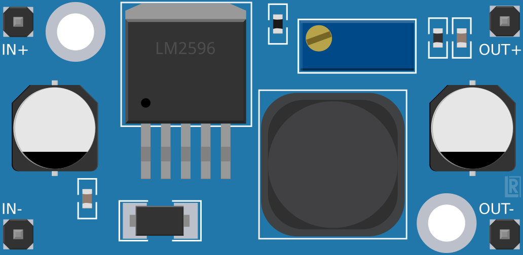
A Step Down converter, also known as a buck converter, is a type of DC-DC converter that reduces voltage from a higher level to a lower level while increasing current. It is widely used in power supply applications due to its high efficiency and ability to handle varying input voltages. Step Down converters are commonly found in battery-powered devices, voltage regulation circuits, and embedded systems where precise voltage levels are required.
Explore Projects Built with Step Down


Explore Projects Built with Step Down
Common Applications:
- Powering microcontrollers and sensors from higher voltage sources
- Voltage regulation in battery-operated devices
- LED drivers and lighting systems
- Industrial and automotive power supplies
Technical Specifications
Key Technical Details:
- Input Voltage Range: Typically 4.5V to 40V (varies by model)
- Output Voltage Range: Adjustable, typically 1.25V to 37V
- Output Current: Up to 3A (depending on the specific module)
- Efficiency: Up to 90% or higher
- Switching Frequency: 150 kHz to 1 MHz (varies by design)
- Thermal Protection: Built-in over-temperature and over-current protection
- Form Factor: Compact PCB module with onboard potentiometer for voltage adjustment
Pin Configuration and Descriptions:
| Pin Name | Description |
|---|---|
| VIN | Input voltage pin. Connect the higher voltage source to this pin. |
| GND | Ground pin. Connect to the ground of the input and output circuits. |
| VOUT | Output voltage pin. Provides the regulated lower voltage to the load. |
| EN (optional) | Enable pin. Used to turn the converter on or off (if available). |
Usage Instructions
How to Use the Step Down Converter in a Circuit:
- Connect the Input Voltage:
- Connect the positive terminal of the power source to the
VINpin. - Connect the negative terminal of the power source to the
GNDpin.
- Connect the positive terminal of the power source to the
- Adjust the Output Voltage:
- Use the onboard potentiometer to set the desired output voltage.
- Measure the output voltage at the
VOUTpin using a multimeter while adjusting.
- Connect the Load:
- Connect the positive terminal of the load to the
VOUTpin. - Connect the negative terminal of the load to the
GNDpin.
- Connect the positive terminal of the load to the
- Power On:
- Turn on the power source and verify the output voltage before connecting sensitive devices.
Important Considerations:
- Ensure the input voltage is within the specified range of the converter.
- Do not exceed the maximum output current rating to avoid overheating or damage.
- Use appropriate heat sinks or cooling mechanisms if operating at high currents.
- Place decoupling capacitors near the input and output pins to reduce noise and improve stability.
Example: Using a Step Down Converter with Arduino UNO
To power an Arduino UNO (operating at 5V) from a 12V battery, follow these steps:
- Connect the 12V battery to the
VINandGNDpins of the Step Down converter. - Adjust the output voltage to 5V using the potentiometer.
- Connect the
VOUTpin of the converter to the Arduino's5Vpin. - Connect the
GNDpin of the converter to the Arduino'sGNDpin.
Here is an example Arduino code to blink an LED while powered by the Step Down converter:
// Blink an LED connected to pin 13 of the Arduino UNO
void setup() {
  pinMode(13, OUTPUT); // Set pin 13 as an output pin
}

void loop() {
  digitalWrite(13, HIGH); // Turn the LED on
  delay(1000);            // Wait for 1 second
  digitalWrite(13, LOW);  // Turn the LED off
  delay(1000);            // Wait for 1 second
}
Troubleshooting and FAQs
Common Issues:
- No Output Voltage:
- Check if the input voltage is within the specified range.
- Verify all connections, especially the
VINandGNDpins. - Ensure the enable pin (if available) is properly configured.
- Output Voltage is Incorrect:
- Re-adjust the potentiometer to set the correct output voltage.
- Verify the load does not exceed the converter's current rating.
- Overheating:
- Ensure proper ventilation or use a heat sink if operating at high currents.
- Check for short circuits or excessive load on the output.
FAQs:
Q: Can I use the Step Down converter to power a Raspberry Pi?
A: Yes, but ensure the output voltage is set to 5V and the converter can supply at least 2.5A for stable operation.Q: What happens if the input voltage drops below the specified range?
A: The converter may stop regulating properly, resulting in unstable or no output voltage.Q: Can I use the Step Down converter with an AC power source?
A: No, the Step Down converter is designed for DC input only. Use a rectifier and filter circuit to convert AC to DC before using the converter.
By following these guidelines, you can effectively use a Step Down converter in your projects while ensuring safety and reliability.