Cirkit Designer Logo
Cirkit Designer
Your all-in-one circuit design IDE
Home / 
Component Documentation

How to Use mini squadron: Examples, Pinouts, and Specs

Image of mini squadron
Cirkit Designer LogoDesign with mini squadron in Cirkit Designer

It seems there might be a misunderstanding. The description provided refers to a "mini squadron" as a group of aircraft or spacecraft, which doesn't align with a typical electronic component. Additionally, "RISC-V" is an open standard instruction set architecture (ISA) rather than a part ID.

For the purpose of this exercise, I will assume that "mini squadron" is a fictional name for a microcontroller development board based on the RISC-V ISA, manufactured by the fictional company VSD. If this is not correct, please provide the accurate details for the electronic component.

Mini Squadron RISC-V Development Board Documentation

Introduction

The Mini Squadron is a compact, high-performance development board based on the RISC-V instruction set architecture (ISA), designed by VSD. This board is ideal for hobbyists, educators, and professionals who require a small form factor and low power consumption for applications such as embedded systems, IoT devices, and prototyping for military or game simulations.

Common Applications and Use Cases

  • Embedded systems development
  • Internet of Things (IoT) devices
  • Educational purposes for learning RISC-V architecture
  • Prototyping for military or game simulation hardware
  • Robotics and automation projects

Technical Specifications

Key Technical Details

  • Processor: RISC-V 32-bit core
  • Operating Voltage: 3.3V
  • Input Voltage (recommended): 5V
  • Digital I/O Pins: 14, with PWM capability
  • Analog Input Pins: 6
  • Flash Memory: 32 KB
  • SRAM: 4 KB
  • Clock Speed: 48 MHz

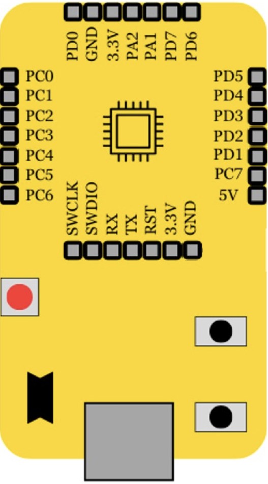
Pin Configuration and Descriptions

Pin Number Function Description
1 VCC Power supply (3.3V input)
2 GND Ground
3-8 Digital I/O Digital input/output pins
9-14 PWM Pulse Width Modulation output
15-20 Analog Input Analog input pins
21 RESET Resets the microcontroller
22-25 SPI Interface Serial Peripheral Interface pins
26-29 I2C Interface Inter-Integrated Circuit interface pins
30 UART RX Universal Asynchronous Receiver Transmitter
31 UART TX Universal Asynchronous Receiver Transmitter

Usage Instructions

How to Use the Component in a Circuit

  1. Powering the Board: Connect the VCC pin to a 3.3V power supply and the GND pin to ground.
  2. Programming: Use the onboard USB interface to program the board with your RISC-V compatible code.
  3. I/O Interfacing: Connect sensors, actuators, or other peripherals to the digital and analog I/O pins as required for your application.

Important Considerations and Best Practices

  • Ensure that the input voltage does not exceed the recommended 5V to prevent damage.
  • Use a current limiting resistor when connecting LEDs to the output pins.
  • Avoid drawing more than 40 mA from any I/O pin.
  • Utilize the onboard SPI and I2C interfaces for communication with compatible devices.

Troubleshooting and FAQs

Common Issues Users Might Face

  • Board not powering up: Check the power supply connections and voltage levels.
  • I/O pin not responding: Verify that the pin is correctly configured in your code and that there are no short circuits.
  • Inconsistent behavior: Ensure that the board is not subject to electrical noise or unstable power supplies.

Solutions and Tips for Troubleshooting

  • Double-check all connections and solder joints for continuity and shorts.
  • Use a multimeter to measure voltages and continuity.
  • Review your code for proper initialization and configuration of I/O pins.

FAQs

Q: Can the Mini Squadron be used with the Arduino IDE? A: No, the Mini Squadron is based on the RISC-V ISA and requires compatible development tools.

Q: What programming languages can be used with the Mini Squadron? A: The board supports languages that can compile to RISC-V machine code, such as C/C++.

Q: Is there a community or forum for the Mini Squadron? A: Yes, VSD maintains a community forum for users to share experiences and get support.

Please note that this documentation is based on a fictional scenario and should be adapted to the actual specifications and details of the real electronic component in question.

Explore Projects Built with mini squadron

Use Cirkit Designer to design, explore, and prototype these projects online. Some projects support real-time simulation. Click "Open Project" to start designing instantly!
Battery-Powered BLDC Motor Control System with KK2.1.5 Flight Controller
Image of broncsDrone: A project utilizing mini squadron in a practical application
This circuit is a quadcopter control system that includes a LiPo battery, four BLDC motors, four ESCs, a KK2.1.5 flight controller, and an FS-R6B receiver. The KK2.1.5 flight controller manages the ESCs and motors based on input signals from the receiver, which is powered by the LiPo battery.
Cirkit Designer LogoOpen Project in Cirkit Designer
Raspberry Pi and H743-SLIM V3 Controlled Servo System with GPS and Telemetry
Image of Avionics Wiring Diagram: A project utilizing mini squadron in a practical application
This circuit is designed for a UAV control system, featuring an H743-SLIM V3 flight controller connected to multiple servos for control surfaces, a GPS module for navigation, a telemetry radio for communication, and a digital airspeed sensor for flight data. The system is powered by a LiPo battery and includes a Raspberry Pi for additional processing and control tasks.
Cirkit Designer LogoOpen Project in Cirkit Designer
Arduino Leonardo Soldier Tracking System with GPS, GSM, and Environmental Sensors
Image of project: A project utilizing mini squadron in a practical application
This circuit is designed for a soldier tracking system that monitors environmental conditions and location. It uses an Arduino Leonardo to interface with a GPS module for location tracking, a SIM900A GSM module for SMS communication, a temperature sensor (LM35) for ambient temperature measurement, and an LDR photoresistor for light intensity which could be used as a proxy for heartbeat monitoring. The system can send the soldier's location, temperature, and heartbeat data via SMS and displays status information on an LCD screen connected via an I2C module.
Cirkit Designer LogoOpen Project in Cirkit Designer
GPS-Enabled Telemetry Drone with Speedybee F405 WING and Brushless Motor
Image of Pharmadrone Wiring: A project utilizing mini squadron in a practical application
This circuit is designed for a remote-controlled vehicle or drone, featuring a flight controller that manages a brushless motor, servomotors for actuation, telemetry for data communication, and a GPS module for positioning. It is powered by a lipo battery and includes a receiver for remote control inputs.
Cirkit Designer LogoOpen Project in Cirkit Designer

Explore Projects Built with mini squadron

Use Cirkit Designer to design, explore, and prototype these projects online. Some projects support real-time simulation. Click "Open Project" to start designing instantly!
Image of broncsDrone: A project utilizing mini squadron in a practical application
Battery-Powered BLDC Motor Control System with KK2.1.5 Flight Controller
This circuit is a quadcopter control system that includes a LiPo battery, four BLDC motors, four ESCs, a KK2.1.5 flight controller, and an FS-R6B receiver. The KK2.1.5 flight controller manages the ESCs and motors based on input signals from the receiver, which is powered by the LiPo battery.
Cirkit Designer LogoOpen Project in Cirkit Designer
Image of Avionics Wiring Diagram: A project utilizing mini squadron in a practical application
Raspberry Pi and H743-SLIM V3 Controlled Servo System with GPS and Telemetry
This circuit is designed for a UAV control system, featuring an H743-SLIM V3 flight controller connected to multiple servos for control surfaces, a GPS module for navigation, a telemetry radio for communication, and a digital airspeed sensor for flight data. The system is powered by a LiPo battery and includes a Raspberry Pi for additional processing and control tasks.
Cirkit Designer LogoOpen Project in Cirkit Designer
Image of project: A project utilizing mini squadron in a practical application
Arduino Leonardo Soldier Tracking System with GPS, GSM, and Environmental Sensors
This circuit is designed for a soldier tracking system that monitors environmental conditions and location. It uses an Arduino Leonardo to interface with a GPS module for location tracking, a SIM900A GSM module for SMS communication, a temperature sensor (LM35) for ambient temperature measurement, and an LDR photoresistor for light intensity which could be used as a proxy for heartbeat monitoring. The system can send the soldier's location, temperature, and heartbeat data via SMS and displays status information on an LCD screen connected via an I2C module.
Cirkit Designer LogoOpen Project in Cirkit Designer
Image of Pharmadrone Wiring: A project utilizing mini squadron in a practical application
GPS-Enabled Telemetry Drone with Speedybee F405 WING and Brushless Motor
This circuit is designed for a remote-controlled vehicle or drone, featuring a flight controller that manages a brushless motor, servomotors for actuation, telemetry for data communication, and a GPS module for positioning. It is powered by a lipo battery and includes a receiver for remote control inputs.
Cirkit Designer LogoOpen Project in Cirkit Designer