How to Use WROOM ESP32: Examples, Pinouts, and Specs
Introduction
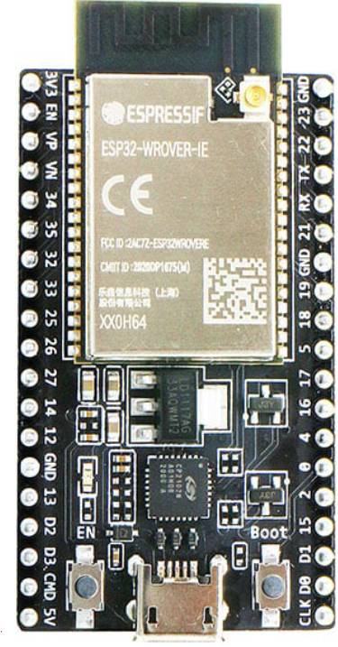
The WROOM ESP32, manufactured by Diy Electronics (Part ID: ESP32 Development Board – USB Type-C), is a powerful and versatile Wi-Fi and Bluetooth module. It integrates a dual-core microcontroller, making it ideal for Internet of Things (IoT) applications. This module is designed to simplify the development of connected devices by offering a rich set of peripherals and support for various communication protocols.
Explore Projects Built with WROOM ESP32


Explore Projects Built with WROOM ESP32
Common Applications and Use Cases
- IoT devices and smart home automation
- Wireless sensor networks
- Wearable technology
- Industrial automation and control systems
- Robotics and drones
- Prototyping and educational projects
Technical Specifications
Key Technical Details
| Parameter | Specification |
|---|---|
| Microcontroller | Dual-core Xtensa® 32-bit LX6 CPU |
| Clock Speed | Up to 240 MHz |
| Flash Memory | 4 MB (default, expandable) |
| SRAM | 520 KB |
| Wireless Connectivity | Wi-Fi 802.11 b/g/n, Bluetooth v4.2 |
| Operating Voltage | 3.3V |
| Input Voltage Range | 5V (via USB Type-C) |
| GPIO Pins | 34 |
| Communication Protocols | UART, SPI, I2C, I2S, CAN, PWM |
| ADC Channels | 18 (12-bit resolution) |
| DAC Channels | 2 |
| Power Consumption | Ultra-low power (varies by mode) |
| Dimensions | 25.5 mm x 18 mm |
Pin Configuration and Descriptions
| Pin Name | Pin Number | Description |
|---|---|---|
| VIN | 1 | Input power supply (5V via USB Type-C) |
| GND | 2 | Ground |
| 3V3 | 3 | 3.3V output for external components |
| EN | 4 | Enable pin (active high) |
| IO0 | 5 | GPIO0, used for boot mode selection |
| IO2 | 6 | GPIO2, general-purpose I/O |
| IO4 | 7 | GPIO4, general-purpose I/O |
| IO5 | 8 | GPIO5, general-purpose I/O |
| IO12 | 9 | GPIO12, general-purpose I/O |
| IO13 | 10 | GPIO13, general-purpose I/O |
| IO14 | 11 | GPIO14, general-purpose I/O |
| IO15 | 12 | GPIO15, general-purpose I/O |
| IO16 | 13 | GPIO16, general-purpose I/O |
| IO17 | 14 | GPIO17, general-purpose I/O |
| TXD0 | 15 | UART0 Transmit |
| RXD0 | 16 | UART0 Receive |
Note: The WROOM ESP32 has additional GPIO pins and peripherals. Refer to the full datasheet for a complete pinout.
Usage Instructions
How to Use the Component in a Circuit
- Powering the Module: Connect the module to a 5V power source using the USB Type-C port. The onboard voltage regulator will step down the voltage to 3.3V for the ESP32.
- Connecting Peripherals: Use the GPIO pins to interface with sensors, actuators, and other devices. Ensure that external components operate at 3.3V logic levels to avoid damaging the module.
- Programming the ESP32:
- Install the Arduino IDE and add the ESP32 board package.
- Connect the module to your computer via USB Type-C.
- Select the appropriate board and port in the Arduino IDE.
- Write and upload your code to the ESP32.
Important Considerations and Best Practices
- Voltage Levels: Avoid applying voltages higher than 3.3V to the GPIO pins.
- Boot Mode: To enter bootloader mode, hold the IO0 pin low while resetting the module.
- Power Consumption: Use deep sleep mode to minimize power consumption in battery-powered applications.
- Antenna Placement: Ensure the onboard antenna is not obstructed by metal objects to maintain optimal wireless performance.
Example Code for Arduino UNO Integration
The following example demonstrates how to connect the WROOM ESP32 to an Arduino UNO for basic communication via UART.
// Example: ESP32 and Arduino UNO UART Communication
// This code sends a message from the Arduino UNO to the ESP32 via UART.

#include <SoftwareSerial.h>

// Define RX and TX pins for SoftwareSerial
SoftwareSerial esp32Serial(10, 11); // RX = 10, TX = 11

void setup() {
  // Initialize serial communication
  Serial.begin(9600); // Arduino Serial Monitor
  esp32Serial.begin(9600); // ESP32 communication

  Serial.println("Arduino UNO is ready to communicate with ESP32.");
}

void loop() {
  // Send a message to the ESP32
  esp32Serial.println("Hello from Arduino UNO!");

  // Check if the ESP32 sent any data
  if (esp32Serial.available()) {
    String message = esp32Serial.readString();
    Serial.println("Message from ESP32: " + message);
  }

  delay(1000); // Wait for 1 second
}
Note: Ensure proper voltage level shifting if connecting the ESP32 directly to the Arduino UNO, as the UNO operates at 5V logic levels.
Troubleshooting and FAQs
Common Issues and Solutions
ESP32 Not Detected by Computer:
- Ensure the USB Type-C cable supports data transfer (not just charging).
- Verify that the correct drivers are installed for the ESP32.
Upload Fails in Arduino IDE:
- Check that the correct board and port are selected in the IDE.
- Hold the IO0 pin low while pressing the reset button to enter bootloader mode.
Wi-Fi Connection Issues:
- Verify the SSID and password in your code.
- Ensure the router is within range and supports 2.4 GHz Wi-Fi.
GPIO Pin Not Responding:
- Confirm that the pin is not being used by another peripheral.
- Check for short circuits or incorrect wiring.
FAQs
Q: Can the WROOM ESP32 operate on battery power?
A: Yes, the module can be powered by a 3.7V LiPo battery connected to the VIN pin, but ensure proper voltage regulation.
Q: Does the ESP32 support over-the-air (OTA) updates?
A: Yes, the ESP32 supports OTA updates, allowing you to upload new firmware wirelessly.
Q: Can I use the ESP32 with MicroPython?
A: Absolutely! The ESP32 is compatible with MicroPython, which is a lightweight Python implementation for microcontrollers.
Q: How do I reset the ESP32?
A: Press the onboard reset button or toggle the EN pin to reset the module.
By following this documentation, you can effectively integrate the WROOM ESP32 into your projects and troubleshoot common issues with ease.