How to Use Voltage and Current Signal Generator: Examples, Pinouts, and Specs
Introduction
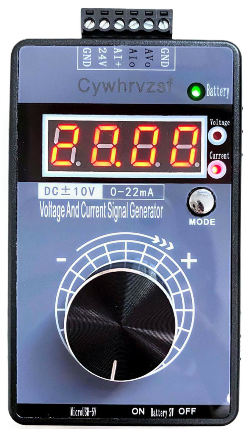
The Voltage and Current Signal Generator is a versatile electronic device designed to produce precise electrical signals in the form of voltage or current. It is commonly used for testing, simulating, and troubleshooting electronic circuits and systems. This component is essential in laboratories, research facilities, and industrial environments where accurate signal generation is required.
Explore Projects Built with Voltage and Current Signal Generator
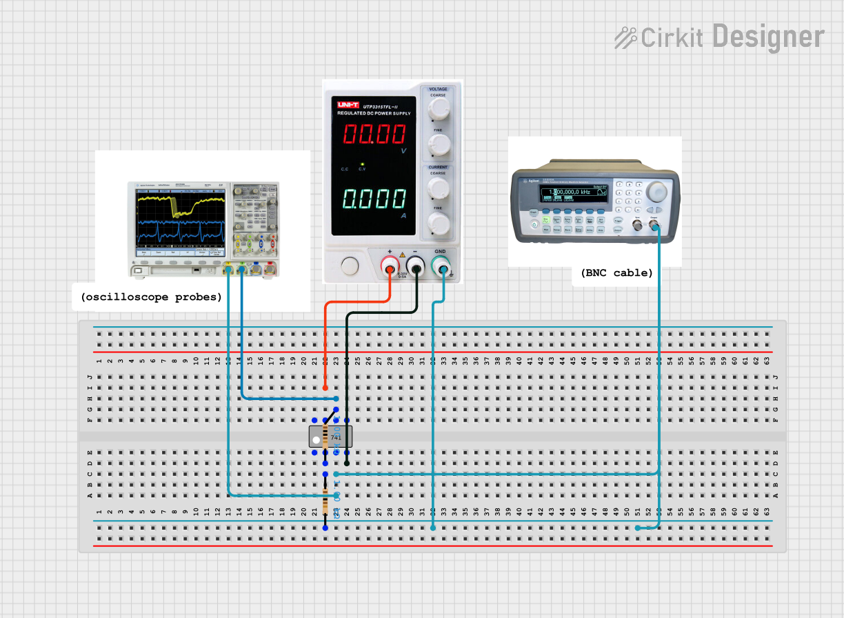
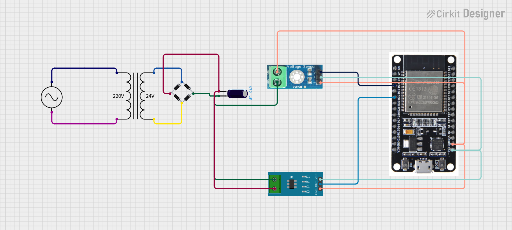
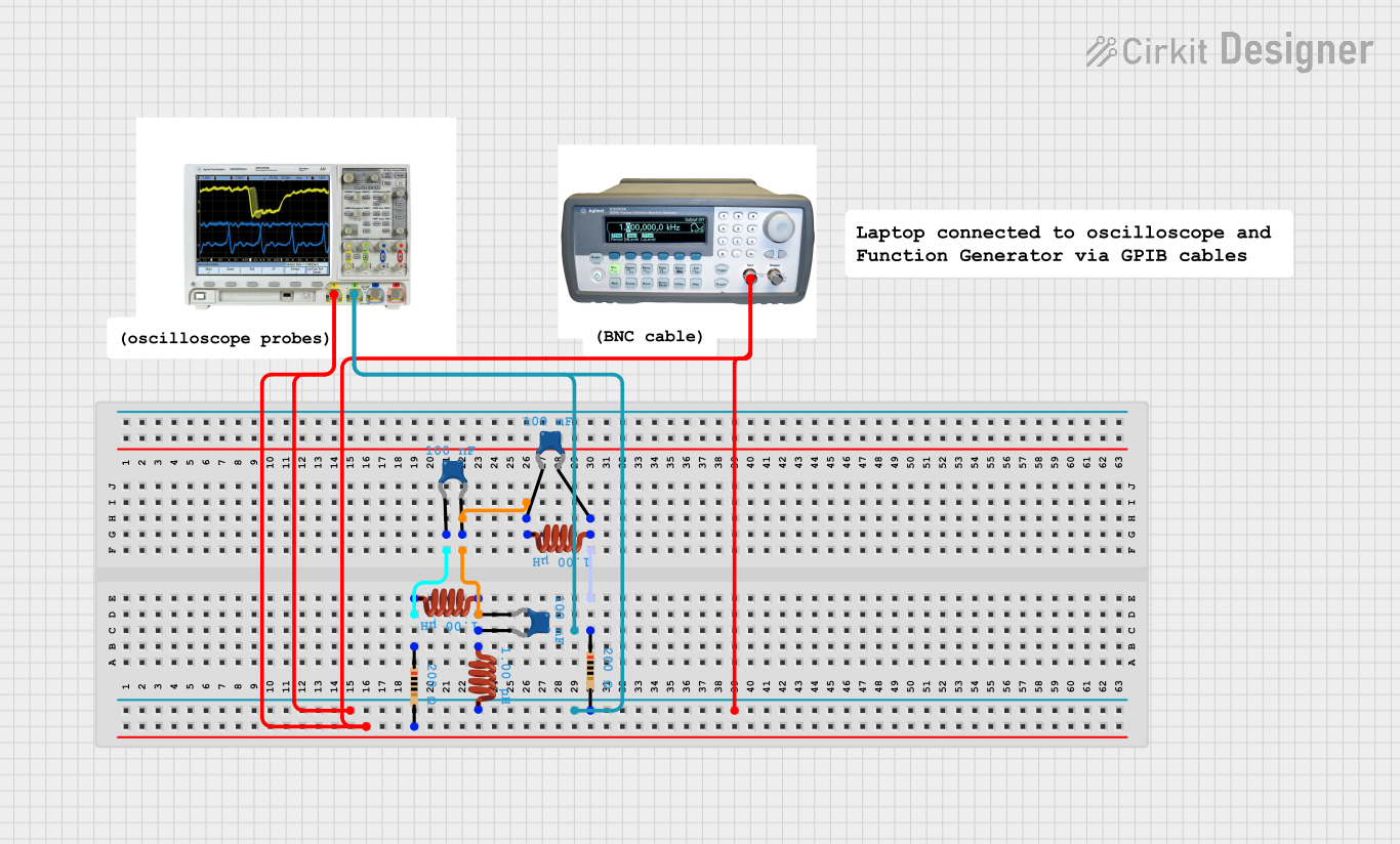

Explore Projects Built with Voltage and Current Signal Generator
Common Applications and Use Cases
- Testing and calibration of electronic circuits
- Simulating sensor outputs for development and debugging
- Generating reference signals for analog and digital systems
- Educational purposes in electronics and engineering labs
- Troubleshooting and diagnosing faults in circuits
Technical Specifications
Below are the key technical details of the Voltage and Current Signal Generator:
| Parameter | Specification |
|---|---|
| Output Voltage Range | 0 V to 10 V (adjustable) |
| Output Current Range | 0 mA to 20 mA (adjustable) |
| Signal Types | DC, Sine, Square, Triangle |
| Frequency Range | 1 Hz to 100 kHz |
| Output Impedance | 50 Ω |
| Power Supply Voltage | 12 V to 24 V DC |
| Accuracy | ±0.1% of full-scale output |
| Operating Temperature | -10°C to 50°C |
| Dimensions | 120 mm x 80 mm x 40 mm |
| Weight | 300 g |
Pin Configuration and Descriptions
The Voltage and Current Signal Generator typically has the following pin configuration:
| Pin Number | Pin Name | Description |
|---|---|---|
| 1 | V+ | Positive power supply input (12 V to 24 V DC) |
| 2 | GND | Ground connection |
| 3 | Voltage Output | Adjustable voltage signal output |
| 4 | Current Output | Adjustable current signal output |
| 5 | Frequency Control | Input for external frequency control (optional) |
| 6 | Mode Select | Selects between voltage or current output modes |
Usage Instructions
How to Use the Component in a Circuit
- Power Connection: Connect the
V+pin to a DC power supply (12 V to 24 V) and theGNDpin to the ground of your circuit. - Mode Selection: Use the
Mode Selectpin to choose between voltage or current output modes. Refer to the manufacturer's datasheet for specific mode selection logic. - Signal Output: Connect the
Voltage OutputorCurrent Outputpin to the input of the circuit you wish to test or simulate. - Frequency Adjustment: If your application requires a specific frequency, use the
Frequency Controlpin to adjust the signal frequency. This can be done via an external potentiometer or microcontroller. - Calibration: For precise applications, calibrate the output using a multimeter or oscilloscope to ensure accuracy.
Important Considerations and Best Practices
- Load Impedance: Ensure the load impedance matches the output impedance (50 Ω) for optimal performance.
- Overload Protection: Avoid exceeding the maximum output voltage or current to prevent damage to the generator or the connected circuit.
- Heat Dissipation: Operate the device in a well-ventilated area to prevent overheating.
- Signal Integrity: Use shielded cables for connections to minimize noise and signal distortion.
- Arduino Integration: The signal generator can be controlled via an Arduino UNO for automated testing. Below is an example code snippet for controlling the frequency using PWM.
// Example Arduino code to control the frequency of the signal generator
// using PWM on pin 9. Ensure the Frequency Control pin is connected to pin 9.

const int pwmPin = 9; // PWM pin connected to Frequency Control
int frequency = 100;  // Desired frequency in Hz (adjustable)

void setup() {
  pinMode(pwmPin, OUTPUT); // Set the PWM pin as output
}

void loop() {
  // Generate a PWM signal with a duty cycle proportional to the frequency
  analogWrite(pwmPin, map(frequency, 1, 1000, 0, 255));

  // Add a delay to stabilize the output
  delay(100);
}
Troubleshooting and FAQs
Common Issues Users Might Face
No Output Signal:
- Cause: Incorrect power supply connection or insufficient voltage.
- Solution: Verify the power supply voltage and polarity. Ensure it is within the specified range (12 V to 24 V DC).
Distorted Signal:
- Cause: Load impedance mismatch or excessive noise.
- Solution: Use a load impedance of 50 Ω and shielded cables to reduce noise.
Overheating:
- Cause: Prolonged operation at maximum output or poor ventilation.
- Solution: Reduce the output level or improve ventilation around the device.
Inaccurate Output:
- Cause: Calibration drift or faulty connections.
- Solution: Recalibrate the output using a multimeter or oscilloscope. Check all connections.
Solutions and Tips for Troubleshooting
- Always double-check the wiring and connections before powering on the device.
- Use a reliable multimeter or oscilloscope to verify the output signal.
- If the device fails to operate, consult the manufacturer's datasheet for additional troubleshooting steps or contact technical support.
By following this documentation, users can effectively utilize the Voltage and Current Signal Generator for a wide range of applications while ensuring optimal performance and reliability.