How to Use Joystick 5-way navigation: Examples, Pinouts, and Specs
Introduction
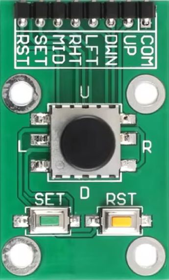
The Joystick 5-Way Navigation (Manufacturer Part ID: 5-way navigation switch Joystick) is a compact and versatile input device that allows for directional control in five positions: up, down, left, right, and center (press). This joystick is commonly used in gaming controllers, navigation devices, and user interfaces where precise directional input is required. Its small size and ease of integration make it ideal for both hobbyist and professional applications.
Explore Projects Built with Joystick 5-way navigation

Explore Projects Built with Joystick 5-way navigation
Common Applications
- Gaming controllers
- Menu navigation in embedded systems
- Robotics control
- DIY electronics projects
- User interface design for consumer electronics
Technical Specifications
Key Technical Details
| Parameter | Value |
|---|---|
| Manufacturer | Generic |
| Part ID | 5-way navigation switch Joystick |
| Operating Voltage | 3.3V to 5V |
| Operating Current | <10mA |
| Contact Resistance | <100mΩ |
| Insulation Resistance | >100MΩ |
| Actuation Force | ~200g (varies by direction) |
| Lifespan | >100,000 cycles |
| Dimensions | ~20mm x 20mm x 15mm |
| Mounting Type | Through-hole or PCB mount |
Pin Configuration and Descriptions
The joystick has five directional outputs and one common ground pin. The pinout is as follows:
| Pin Number | Label | Description |
|---|---|---|
| 1 | UP | Output signal for upward movement |
| 2 | DOWN | Output signal for downward movement |
| 3 | LEFT | Output signal for leftward movement |
| 4 | RIGHT | Output signal for rightward movement |
| 5 | CENTER | Output signal for center press |
| 6 | GND | Ground connection for the joystick |
Usage Instructions
How to Use the Joystick in a Circuit
Wiring the Joystick:
- Connect the
GNDpin of the joystick to the ground of your circuit. - Connect each directional pin (
UP,DOWN,LEFT,RIGHT,CENTER) to a digital input pin on your microcontroller or other input device. - Use pull-up or pull-down resistors if required by your circuit design.
- Connect the
Reading the Joystick State:
- Each directional pin outputs a signal when the joystick is moved in the corresponding direction or pressed in the center.
- Monitor the state of these pins using a microcontroller to detect user input.
Example Circuit:
- Connect the joystick to an Arduino UNO as follows:
UPto digital pin 2DOWNto digital pin 3LEFTto digital pin 4RIGHTto digital pin 5CENTERto digital pin 6GNDto Arduino GND
- Connect the joystick to an Arduino UNO as follows:
Arduino Code Example
Below is an example Arduino sketch to read the joystick's state and print the direction to the Serial Monitor:
// Pin definitions for the joystick
const int pinUp = 2;
const int pinDown = 3;
const int pinLeft = 4;
const int pinRight = 5;
const int pinCenter = 6;

void setup() {
  // Initialize serial communication
  Serial.begin(9600);

  // Set joystick pins as inputs
  pinMode(pinUp, INPUT);
  pinMode(pinDown, INPUT);
  pinMode(pinLeft, INPUT);
  pinMode(pinRight, INPUT);
  pinMode(pinCenter, INPUT);
}

void loop() {
  // Check each direction and print the state
  if (digitalRead(pinUp) == HIGH) {
    Serial.println("Joystick moved UP");
  }
  if (digitalRead(pinDown) == HIGH) {
    Serial.println("Joystick moved DOWN");
  }
  if (digitalRead(pinLeft) == HIGH) {
    Serial.println("Joystick moved LEFT");
  }
  if (digitalRead(pinRight) == HIGH) {
    Serial.println("Joystick moved RIGHT");
  }
  if (digitalRead(pinCenter) == HIGH) {
    Serial.println("Joystick pressed CENTER");
  }

  // Small delay to avoid spamming the Serial Monitor
  delay(100);
}
Important Considerations and Best Practices
- Debouncing: Mechanical switches can produce noise or "bouncing" when actuated. Use software debouncing techniques or external capacitors to ensure stable readings.
- Voltage Compatibility: Ensure the joystick's operating voltage matches your microcontroller's input voltage levels (e.g., 3.3V or 5V).
- Pull-up Resistors: If the joystick outputs are open-drain or floating, use pull-up resistors to ensure reliable signal detection.
- Mechanical Stress: Avoid applying excessive force to the joystick to prevent damage.
Troubleshooting and FAQs
Common Issues and Solutions
Joystick Not Responding:
- Verify all connections, especially the
GNDpin. - Check if the joystick's operating voltage matches your circuit's power supply.
- Verify all connections, especially the
Incorrect or Erratic Readings:
- Implement software debouncing to filter out noise.
- Ensure proper pull-up or pull-down resistors are used if required.
Directional Pins Always HIGH or LOW:
- Check for short circuits or loose connections.
- Verify that the microcontroller's input pins are configured correctly.
Joystick Feels Stiff or Unresponsive:
- Inspect for physical damage or debris obstructing movement.
- Replace the joystick if it has exceeded its lifespan.
FAQs
Q: Can this joystick be used with a Raspberry Pi?
A: Yes, the joystick can be connected to the GPIO pins of a Raspberry Pi. Use appropriate pull-up resistors and ensure the voltage levels are compatible.
Q: Is the joystick waterproof?
A: No, this joystick is not waterproof. Avoid exposing it to moisture or liquids.
Q: Can I use this joystick for analog input?
A: No, this joystick provides digital signals for each direction. For analog input, consider using an analog joystick module.
Q: How do I mount the joystick on a PCB?
A: The joystick is designed for through-hole mounting. Align the pins with the PCB holes and solder them securely.
By following this documentation, you can effectively integrate the Joystick 5-Way Navigation into your projects and troubleshoot any issues that arise.