
How to Use QFN-32: Examples, Pinouts, and Specs
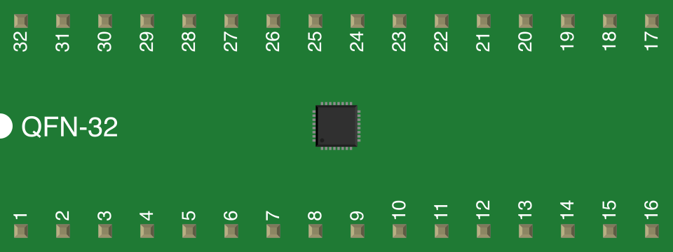
 Design with QFN-32 in Cirkit Designer
Introduction
The QFN-32 (Quad Flat No-lead, 32 pins) is a surface-mount integrated circuit (IC) package designed for applications requiring compact size and efficient thermal performance. Its leadless design minimizes the footprint on printed circuit boards (PCBs), making it ideal for space-constrained applications. The exposed thermal pad on the underside of the package enhances heat dissipation, ensuring reliable operation in high-performance systems.
Explore Projects Built with QFN-32
 Open Project in Cirkit Designer
 Open Project in Cirkit Designer
 Open Project in Cirkit Designer
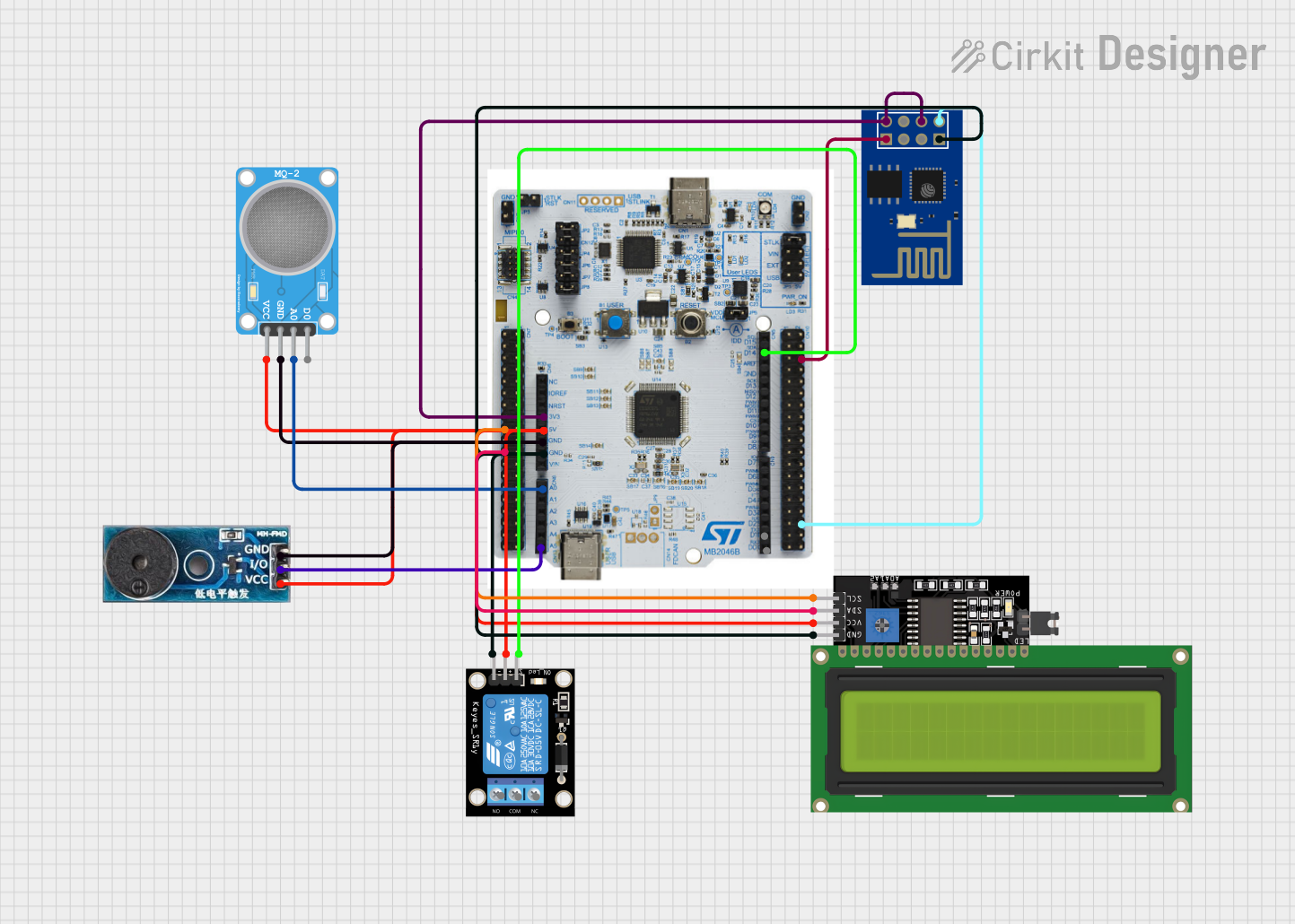 Open Project in Cirkit Designer
Explore Projects Built with QFN-32
Open Project in Cirkit DesignerOpen Project in Cirkit DesignerOpen Project in Cirkit DesignerOpen Project in Cirkit DesignerCommon Applications
- Mobile devices and wearables
- Consumer electronics
- Automotive systems
- Industrial control systems
- Wireless communication modules
Technical Specifications
Key Technical Details
| Parameter | Value/Description |
|---|---|
| Package Type | Quad Flat No-lead (QFN) |
| Pin Count | 32 |
| Dimensions | Typically 5 mm x 5 mm (varies by manufacturer) |
| Pitch (Pin Spacing) | 0.5 mm |
| Mounting Type | Surface Mount Technology (SMT) |
| Thermal Pad | Exposed pad for heat dissipation |
| Operating Temperature | -40°C to +125°C (varies by IC specification) |
| Moisture Sensitivity | Level 3 (typical, per JEDEC standards) |
Pin Configuration and Descriptions
The QFN-32 package has 32 pins arranged around the perimeter of the package, with an exposed thermal pad at the center. The pin functions depend on the specific IC housed in the QFN-32 package. Below is a generic example of pin configuration for a microcontroller in a QFN-32 package:
| Pin Number | Pin Name | Description |
|---|---|---|
| 1 | VDD | Power supply |
| 2 | GND | Ground |
| 3 | GPIO1 | General-purpose input/output |
| 4 | GPIO2 | General-purpose input/output |
| 5 | TX | UART Transmit |
| 6 | RX | UART Receive |
| 7 | SCL | I2C Clock |
| 8 | SDA | I2C Data |
| 9-30 | GPIO/Other | Configurable pins (varies by IC) |
| 31 | RESET | Reset pin |
| 32 | NC | No connection (varies by IC) |
| Center Pad | Thermal Pad | Connect to ground plane for heat dissipation |
Note: Always refer to the datasheet of the specific IC for exact pin assignments.
Usage Instructions
How to Use the QFN-32 in a Circuit
PCB Design:
- Ensure the PCB layout matches the QFN-32 footprint, including the exposed thermal pad.
- Use solder mask-defined (SMD) pads for better soldering accuracy.
- Include thermal vias under the thermal pad to connect it to a ground plane for heat dissipation.
Soldering:
- Use reflow soldering for mounting the QFN-32 package.
- Apply solder paste evenly on the pads and thermal pad.
- Follow the recommended reflow temperature profile provided by the IC manufacturer.
Thermal Management:
- Connect the exposed thermal pad to a large ground plane or dedicated heat sink.
- Use thermal vias to improve heat transfer to other PCB layers.
Testing and Debugging:
- Use test points on critical pins (e.g., power, ground, communication lines) for debugging.
- Verify solder joints under a microscope or with X-ray inspection.
Important Considerations
- Moisture Sensitivity: QFN packages are sensitive to moisture. Store them in a dry environment and bake them before soldering if necessary.
- Handling: Avoid touching the pins or thermal pad to prevent contamination.
- Alignment: Ensure precise alignment of the package with the PCB pads during placement.
Example: Connecting a QFN-32 Microcontroller to an Arduino UNO
If the QFN-32 package houses a microcontroller, you can interface it with an Arduino UNO using UART or I2C. Below is an example of Arduino code for I2C communication:
#include <Wire.h> // Include the Wire library for I2C communication

#define QFN_DEVICE_ADDRESS 0x40 // Replace with the actual I2C address of the QFN device

void setup() {
  Wire.begin(); // Initialize I2C communication
  Serial.begin(9600); // Initialize serial communication for debugging

  // Send a test command to the QFN device
  Wire.beginTransmission(QFN_DEVICE_ADDRESS);
  Wire.write(0x01); // Example command to the QFN device
  Wire.endTransmission();

  Serial.println("I2C communication initialized.");
}

void loop() {
  Wire.requestFrom(QFN_DEVICE_ADDRESS, 1); // Request 1 byte from the QFN device

  if (Wire.available()) {
    int data = Wire.read(); // Read the received byte
    Serial.print("Received data: ");
    Serial.println(data);
  }

  delay(1000); // Wait for 1 second before the next request
}
Note: Replace QFN_DEVICE_ADDRESS and commands with values specific to your IC.
Troubleshooting and FAQs
Common Issues and Solutions
Issue: Poor solder joints or misalignment.
- Solution: Use a stencil for solder paste application and ensure precise placement during assembly.
Issue: Overheating of the IC.
- Solution: Verify that the thermal pad is properly connected to a ground plane with sufficient thermal vias.
Issue: Moisture-related damage during soldering.
- Solution: Store QFN packages in a dry environment and bake them before soldering if required.
Issue: Communication failure (e.g., I2C or UART).
- Solution: Check the pin connections, ensure pull-up resistors are used for I2C, and verify the IC's address or baud rate.
FAQs
Q1: Can I hand-solder a QFN-32 package?
A1: Hand-soldering is challenging due to the small pin pitch and the thermal pad. Reflow soldering is recommended, but with proper tools and techniques, hand-soldering is possible for prototypes.
Q2: How do I inspect solder joints under a QFN package?
A2: Use X-ray inspection or a microscope to verify solder joint quality, especially for the thermal pad.
Q3: What is the purpose of the exposed thermal pad?
A3: The thermal pad improves heat dissipation, ensuring reliable operation of the IC in high-performance applications.
Q4: Can I leave the thermal pad unconnected?
A4: No, leaving the thermal pad unconnected can lead to overheating and reduced performance. Always connect it to a ground plane or heat sink.
This concludes the QFN-32 documentation. Always refer to the specific IC datasheet for detailed information and guidelines.