Cirkit Designer Logo
Cirkit Designer
Your all-in-one circuit design IDE
Home / 
Component Documentation

How to Use Trimmer Potentiometer: Examples, Pinouts, and Specs

Image of Trimmer Potentiometer
Cirkit Designer LogoDesign with Trimmer Potentiometer in Cirkit Designer

Introduction

A trimmer potentiometer, commonly referred to as a trim pot, is a miniature adjustable resistor used for adjusting, tuning, and calibrating circuits. Unlike standard potentiometers, trim pots are designed for occasional adjustment and are not intended for regular user interaction. They are commonly found in electronic devices where precise voltage adjustment is necessary, such as in setting the sensitivity of sensors, adjusting the timing of circuits, or calibrating signal levels.

Explore Projects Built with Trimmer Potentiometer

Use Cirkit Designer to design, explore, and prototype these projects online. Some projects support real-time simulation. Click "Open Project" to start designing instantly!
Arduino UNO Analog Input with Trimmer Potentiometer
Image of Potenciometer: A project utilizing Trimmer Potentiometer in a practical application
This circuit features an Arduino UNO connected to a trimmer potentiometer. The potentiometer's adjustable output is fed into the Arduino's analog input A0 for voltage measurement, enabling the microcontroller to monitor or control an analog parameter.
Cirkit Designer LogoOpen Project in Cirkit Designer
Arduino UNO Based Variable Voltage Divider
Image of bcu_lesson2: A project utilizing Trimmer Potentiometer in a practical application
This circuit features an Arduino UNO connected to a trimmer potentiometer. The potentiometer is configured as a voltage divider with one end connected to the Arduino's 5V supply, the other end to GND, and the wiper connected to analog input A5. The purpose of this circuit is to provide an adjustable voltage input to the Arduino for analog sensing.
Cirkit Designer LogoOpen Project in Cirkit Designer
Arduino 101 Analog Input Control with Trimmer Potentiometer
Image of Analog read potentiometer: A project utilizing Trimmer Potentiometer in a practical application
This circuit features an Arduino 101 connected to a trimmer potentiometer. The potentiometer is used as a voltage divider, with one end connected to the Arduino's VIN for power, the wiper connected to analog input A0 for variable voltage reading, and the other end connected to GND. This setup allows the Arduino to read the position of the potentiometer's wiper as an analog value.
Cirkit Designer LogoOpen Project in Cirkit Designer
Arduino UNO Controlled Trimmer Potentiometer
Image of Pot with arduino sim test: A project utilizing Trimmer Potentiometer in a practical application
This circuit features an Arduino UNO connected to a trimmer potentiometer. The Arduino is configured to set one leg of the potentiometer high (D4) and the other low (D3), with the wiper connected to D5, likely for analog input. The purpose of this circuit is to allow the Arduino to read a variable voltage level from the potentiometer, which can be adjusted by turning the trimmer.
Cirkit Designer LogoOpen Project in Cirkit Designer

Explore Projects Built with Trimmer Potentiometer

Use Cirkit Designer to design, explore, and prototype these projects online. Some projects support real-time simulation. Click "Open Project" to start designing instantly!
Image of Potenciometer: A project utilizing Trimmer Potentiometer in a practical application
Arduino UNO Analog Input with Trimmer Potentiometer
This circuit features an Arduino UNO connected to a trimmer potentiometer. The potentiometer's adjustable output is fed into the Arduino's analog input A0 for voltage measurement, enabling the microcontroller to monitor or control an analog parameter.
Cirkit Designer LogoOpen Project in Cirkit Designer
Image of bcu_lesson2: A project utilizing Trimmer Potentiometer in a practical application
Arduino UNO Based Variable Voltage Divider
This circuit features an Arduino UNO connected to a trimmer potentiometer. The potentiometer is configured as a voltage divider with one end connected to the Arduino's 5V supply, the other end to GND, and the wiper connected to analog input A5. The purpose of this circuit is to provide an adjustable voltage input to the Arduino for analog sensing.
Cirkit Designer LogoOpen Project in Cirkit Designer
Image of Analog read potentiometer: A project utilizing Trimmer Potentiometer in a practical application
Arduino 101 Analog Input Control with Trimmer Potentiometer
This circuit features an Arduino 101 connected to a trimmer potentiometer. The potentiometer is used as a voltage divider, with one end connected to the Arduino's VIN for power, the wiper connected to analog input A0 for variable voltage reading, and the other end connected to GND. This setup allows the Arduino to read the position of the potentiometer's wiper as an analog value.
Cirkit Designer LogoOpen Project in Cirkit Designer
Image of Pot with arduino sim test: A project utilizing Trimmer Potentiometer in a practical application
Arduino UNO Controlled Trimmer Potentiometer
This circuit features an Arduino UNO connected to a trimmer potentiometer. The Arduino is configured to set one leg of the potentiometer high (D4) and the other low (D3), with the wiper connected to D5, likely for analog input. The purpose of this circuit is to allow the Arduino to read a variable voltage level from the potentiometer, which can be adjusted by turning the trimmer.
Cirkit Designer LogoOpen Project in Cirkit Designer

Technical Specifications

Key Technical Details

  • Resistance Range: Typically from 500 ohms to 1 megaohm
  • Tolerance: ±10% or better
  • Rated Power: Generally around 0.5W to 1W
  • Operating Temperature Range: -55°C to 125°C
  • Adjustment Type: Top or side adjustment using a screwdriver
  • Mounting Type: Through-hole or surface mount

Pin Configuration and Descriptions

Pin Number Description
1 Counter-clockwise end (CCW)
2 Wiper (adjustable output)
3 Clockwise end (CW)

Usage Instructions

Incorporating into a Circuit

To use a trimmer potentiometer in a circuit:

  1. Identify the Pins: Locate the three pins - CCW, Wiper, and CW.
  2. Mounting: Secure the trim pot on the PCB with proper orientation.
  3. Wiring: Connect the CCW and CW pins to the circuit where variable resistance is needed. The wiper pin will provide the adjustable output.
  4. Adjustment: Use a non-conductive screwdriver to adjust the resistance. Turn clockwise to increase and counter-clockwise to decrease the resistance.

Best Practices

  • Avoid applying excessive force when adjusting to prevent damage.
  • Use a trim pot with a suitable resistance range for your application.
  • Ensure the power rating is not exceeded to avoid overheating.
  • For stable performance, operate within the specified temperature range.

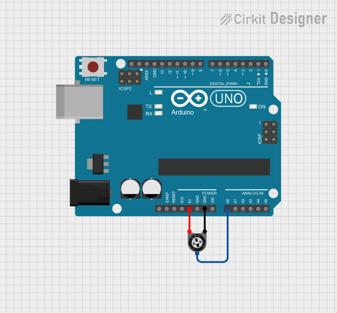
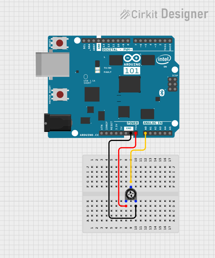
Example with Arduino UNO

Here's how to connect a trimmer potentiometer to an Arduino UNO and read its value:

// Define the pin connected to the trim pot wiper
const int trimPotPin = A0;

void setup() {
  // Initialize serial communication at 9600 bits per second:
  Serial.begin(9600);
}

void loop() {
  // Read the value from the trim pot
  int potValue = analogRead(trimPotPin);
  
  // Convert the reading (which goes from 0 - 1023) to a voltage (0 - 5V):
  float voltage = potValue * (5.0 / 1023.0);
  
  // Print out the value in volts
  Serial.println(voltage);
  
  // Delay for a bit to avoid spamming the serial output
  delay(500);
}

Troubleshooting and FAQs

Common Issues

  • Inconsistent Output: Ensure the trim pot is not damaged and is properly mounted.
  • No Output Change: Verify that the wiper is making good contact and the pot is not at its end limits.
  • Noise in Signal: Check for loose connections and consider using a contact cleaner on the trim pot.

FAQs

Q: How do I know which way to turn the trim pot to increase resistance? A: Typically, turning the screw clockwise increases resistance, while turning it counter-clockwise decreases it.

Q: Can I replace a trim pot with a regular potentiometer? A: Yes, if the specifications match, but regular potentiometers are larger and meant for frequent adjustments.

Q: How do I solder a trim pot without damaging it? A: Use a heat sink, such as a pair of tweezers, to absorb excess heat during soldering.

Q: What tool should I use to adjust a trim pot? A: A small, flat-head screwdriver is typically used, but some trim pots may require a Phillips head or a specialized tool.

Remember, this documentation is a starting point. Always consult the specific datasheet for the trim pot you are using for the most accurate and detailed information.