
How to Use Adafruit MOSFET Driver: Examples, Pinouts, and Specs
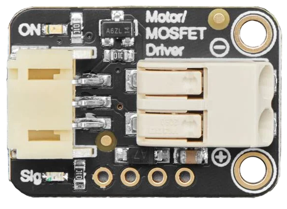
 Design with Adafruit MOSFET Driver in Cirkit Designer
Introduction
The Adafruit MOSFET Driver is a specialized driver designed to control MOSFETs (Metal-Oxide-Semiconductor Field-Effect Transistors) efficiently. It enables high-speed switching and improved performance in various electronic applications. This driver is particularly useful in scenarios where precise control of high-power loads is required, such as motor control, LED dimming, and power regulation circuits.
Explore Projects Built with Adafruit MOSFET Driver
 Open Project in Cirkit Designer
 Open Project in Cirkit Designer
 Open Project in Cirkit Designer
 Open Project in Cirkit Designer
Explore Projects Built with Adafruit MOSFET Driver
Open Project in Cirkit DesignerOpen Project in Cirkit DesignerOpen Project in Cirkit DesignerOpen Project in Cirkit DesignerCommon Applications:
- Motor drivers for robotics and automation
- High-power LED lighting systems
- DC-DC converters and power supplies
- Signal amplification and switching circuits
Technical Specifications
The Adafruit MOSFET Driver is designed to interface between low-power control signals (e.g., from a microcontroller) and high-power MOSFETs. Below are the key technical details:
Key Specifications:
- Input Voltage Range: 3.3V to 20V
- Output Drive Voltage: Up to 20V (dependent on input voltage)
- Peak Output Current: 2A
- Switching Frequency: Up to 1 MHz
- Operating Temperature Range: -40°C to 125°C
- Input Logic Levels: Compatible with 3.3V and 5V logic
- Package Type: DIP or SMD (varies by model)
Pin Configuration and Descriptions:
| Pin Name | Pin Number | Description |
|---|---|---|
| VDD | 1 | Power supply input (3.3V to 20V). |
| GND | 2 | Ground connection. |
| IN | 3 | Logic input signal to control the MOSFET. |
| OUT | 4 | Output signal to drive the MOSFET gate. |
| EN | 5 | Enable pin (active high). Enables the driver. |
Usage Instructions
The Adafruit MOSFET Driver is straightforward to use in a circuit. Below are the steps and considerations for proper usage:
Steps to Use:
Power the Driver:
- Connect the VDD pin to a power source within the specified voltage range (3.3V to 20V).
- Connect the GND pin to the ground of your circuit.
Connect the Logic Input:
- Connect the IN pin to the control signal from your microcontroller or logic circuit.
- Ensure the input logic level matches the driver’s specifications (3.3V or 5V).
Connect the Output to the MOSFET:
- Connect the OUT pin to the gate of the MOSFET you wish to control.
- Ensure the MOSFET is compatible with the driver’s output voltage and current.
Enable the Driver:
- If the EN pin is available, connect it to a high logic level to enable the driver.
- If unused, tie the EN pin to VDD to keep the driver always enabled.
Test the Circuit:
- Apply the desired control signal to the IN pin and observe the MOSFET switching behavior.
Important Considerations:
- Gate Capacitance: Ensure the MOSFET’s gate capacitance is within the driver’s capability to charge and discharge efficiently.
- Heat Dissipation: For high-frequency or high-current applications, ensure proper heat dissipation for both the driver and the MOSFET.
- Decoupling Capacitor: Place a decoupling capacitor (e.g., 0.1 µF) close to the VDD pin to stabilize the power supply.
Example Code for Arduino UNO:
Below is an example of how to use the Adafruit MOSFET Driver with an Arduino UNO to control a MOSFET for switching an LED:
// Define the pin connected to the IN pin of the MOSFET driver
const int mosfetDriverPin = 9;

void setup() {
  // Set the MOSFET driver pin as an output
  pinMode(mosfetDriverPin, OUTPUT);
}

void loop() {
  // Turn the MOSFET (and connected load) ON
  digitalWrite(mosfetDriverPin, HIGH);
  delay(1000); // Keep it ON for 1 second

  // Turn the MOSFET (and connected load) OFF
  digitalWrite(mosfetDriverPin, LOW);
  delay(1000); // Keep it OFF for 1 second
}
Notes:
- Ensure the Arduino’s output pin is connected to the IN pin of the driver.
- The OUT pin of the driver should be connected to the gate of the MOSFET.
Troubleshooting and FAQs
Common Issues:
MOSFET Not Switching:
- Cause: Incorrect wiring or insufficient input voltage.
- Solution: Double-check all connections and ensure the VDD pin is powered correctly.
Driver Overheating:
- Cause: Excessive switching frequency or high gate capacitance.
- Solution: Reduce the switching frequency or use a MOSFET with lower gate capacitance.
No Output Signal:
- Cause: EN pin not enabled or faulty driver.
- Solution: Ensure the EN pin is tied high or connected to VDD. Replace the driver if necessary.
Erratic Behavior:
- Cause: Noise on the power supply or input signal.
- Solution: Add a decoupling capacitor near the VDD pin and use shielded cables for the input signal.
FAQs:
Can I use this driver with a 12V power supply?
- Yes, the driver supports input voltages up to 20V, so 12V is within the acceptable range.
What type of MOSFETs can I use with this driver?
- The driver is compatible with both N-channel and P-channel MOSFETs, provided their gate voltage requirements match the driver’s output.
Is it compatible with 3.3V logic?
- Yes, the driver supports both 3.3V and 5V logic levels for the IN pin.
Can I use this driver for PWM control?
- Absolutely! The driver supports high-speed switching, making it ideal for PWM applications.
By following this documentation, you can effectively integrate the Adafruit MOSFET Driver into your projects for efficient and reliable MOSFET control.