How to Use GP2YOA21YKOF IR Sensor : Examples, Pinouts, and Specs
Introduction
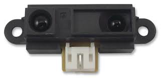
The GP2YOA21YK0F is an infrared (IR) sensor manufactured by Sharp, designed for distance measurement. It operates within a range of 10 to 80 cm and provides an analog voltage output proportional to the distance to the object. This sensor is widely used in robotics, automation, and proximity sensing applications due to its reliability and ease of integration.
Explore Projects Built with GP2YOA21YKOF IR Sensor
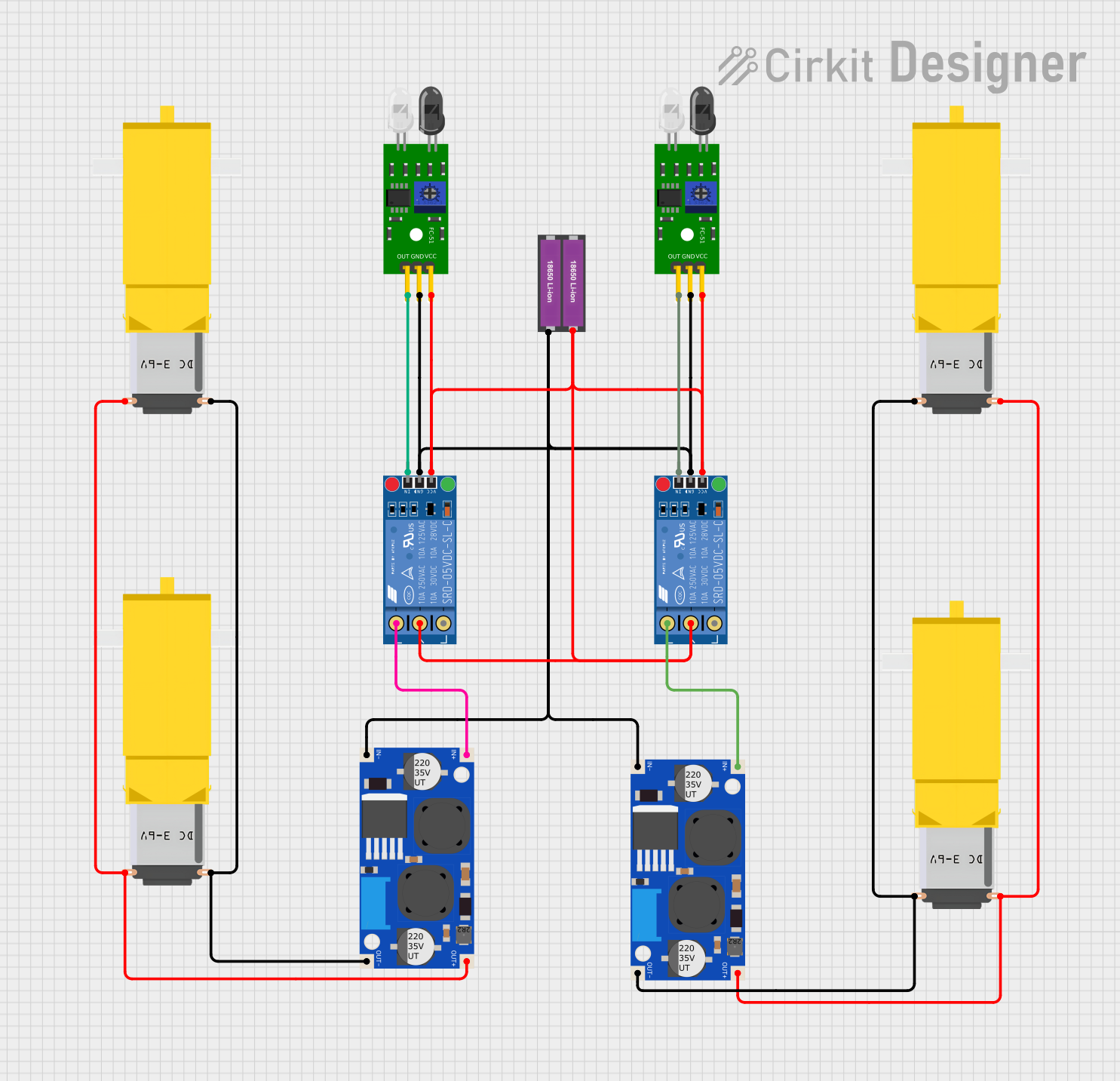

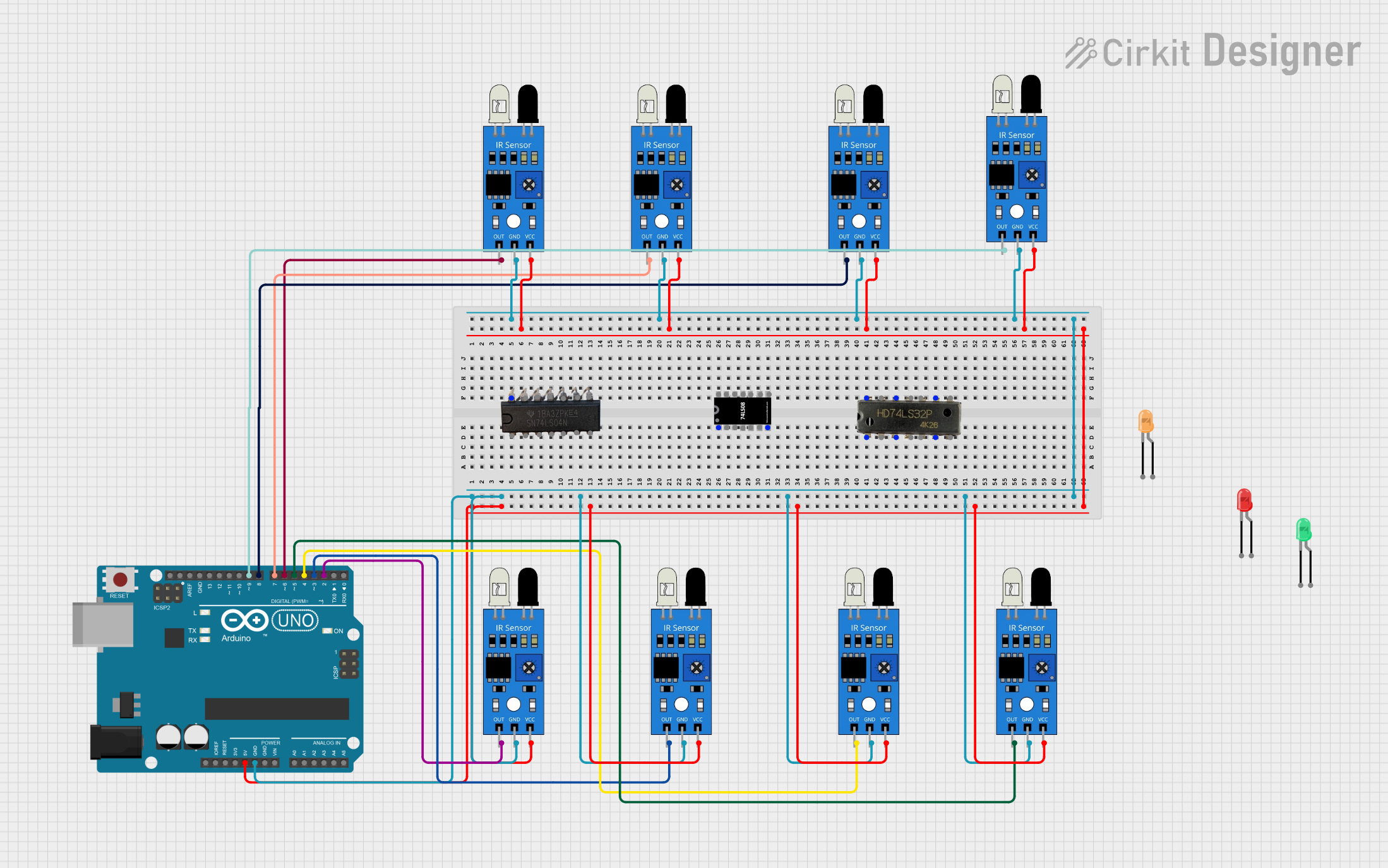
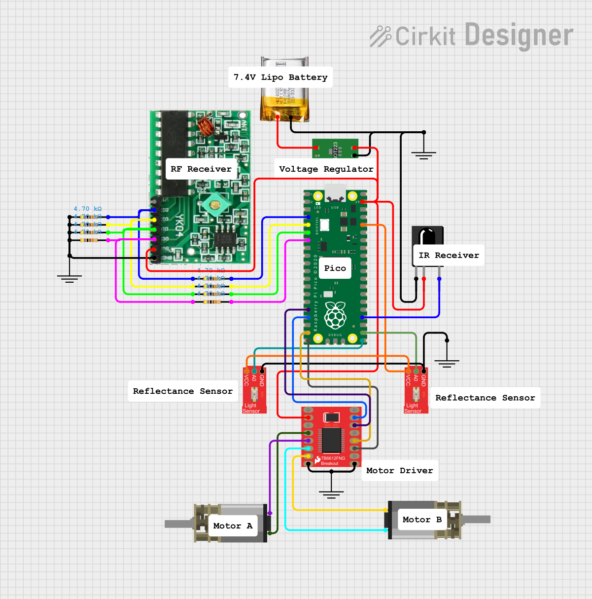
Explore Projects Built with GP2YOA21YKOF IR Sensor
Technical Specifications
Key Technical Details
| Parameter | Value |
|---|---|
| Manufacturer | Sharp |
| Part Number | GP2YOA21YK0F |
| Operating Voltage | 4.5V to 5.5V |
| Average Current Consumption | 30 mA |
| Distance Measuring Range | 10 cm to 80 cm |
| Output Type | Analog Voltage |
| Output Voltage Range | 0.4V to 2.4V |
| Response Time | 38 ms |
| Operating Temperature | -10°C to +60°C |
Pin Configuration and Descriptions
| Pin Number | Pin Name | Description |
|---|---|---|
| 1 | VCC | Power supply (4.5V to 5.5V) |
| 2 | GND | Ground |
| 3 | Vout | Analog voltage output proportional to distance |
Usage Instructions
How to Use the Component in a Circuit
- Power Supply: Connect the VCC pin to a 5V power supply and the GND pin to the ground of your circuit.
- Output Signal: Connect the Vout pin to an analog input pin of a microcontroller (e.g., Arduino UNO) to read the distance measurement.
Important Considerations and Best Practices
- Power Supply: Ensure a stable 5V power supply to avoid fluctuations in the sensor's output.
- Mounting: Mount the sensor securely to avoid vibrations that could affect the accuracy of the measurements.
- Interference: Avoid placing the sensor near sources of infrared interference, such as direct sunlight or other IR-emitting devices.
- Calibration: Calibrate the sensor in your specific environment to account for any variations in readings.
Example Circuit with Arduino UNO
**Components Needed:**
- GP2YOA21YK0F IR Sensor
- Arduino UNO
- Breadboard and jumper wires

**Circuit Diagram:**

Sample Arduino Code
/*
  GP2YOA21YK0F IR Sensor Example
  This code reads the analog voltage output from the GP2YOA21YK0F IR sensor
  and converts it to a distance measurement.
*/

const int sensorPin = A0; // Analog input pin connected to Vout of the sensor
int sensorValue = 0;      // Variable to store the sensor value
float distance = 0;       // Variable to store the calculated distance

void setup() {
  Serial.begin(9600); // Initialize serial communication at 9600 baud
}

void loop() {
  sensorValue = analogRead(sensorPin); // Read the analog value from the sensor
  distance = map(sensorValue, 0, 1023, 10, 80); // Convert the analog value to distance
  Serial.print("Distance: ");
  Serial.print(distance);
  Serial.println(" cm");
  delay(100); // Wait for 100 milliseconds before the next reading
}
Troubleshooting and FAQs
Common Issues Users Might Face
- Inaccurate Readings: The sensor may provide inaccurate readings if not properly calibrated or if there is interference from other IR sources.
- No Output: Ensure that the sensor is correctly powered and that all connections are secure.
- Fluctuating Readings: This can be caused by an unstable power supply or vibrations affecting the sensor.
Solutions and Tips for Troubleshooting
- Check Connections: Verify that all connections are secure and that the sensor is properly powered.
- Stable Power Supply: Use a regulated power supply to ensure stable voltage.
- Calibration: Perform calibration in the specific environment where the sensor will be used.
- Shielding: Shield the sensor from direct sunlight or other IR sources to avoid interference.
FAQs
Q: Can the GP2YOA21YK0F detect objects beyond 80 cm? A: No, the sensor is designed to measure distances within the range of 10 to 80 cm.
Q: How do I calibrate the sensor? A: Calibration involves comparing the sensor's output with known distances and adjusting your code or setup accordingly.
Q: Can I use the sensor in outdoor environments? A: The sensor can be used outdoors, but it should be protected from direct sunlight and extreme weather conditions.
This documentation provides a comprehensive guide to using the GP2YOA21YK0F IR sensor, ensuring both beginners and experienced users can effectively integrate it into their projects.