How to Use rgb button common cathode: Examples, Pinouts, and Specs
Introduction
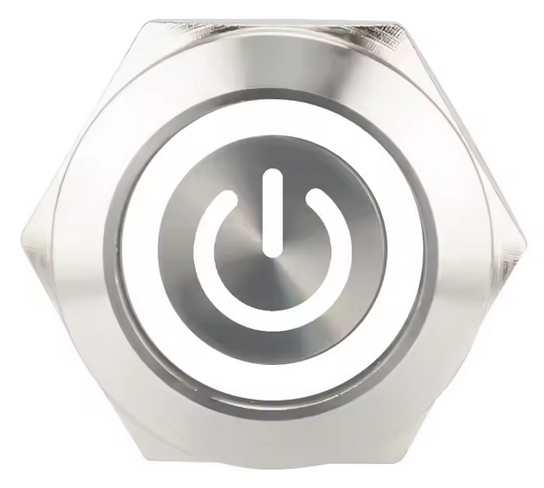
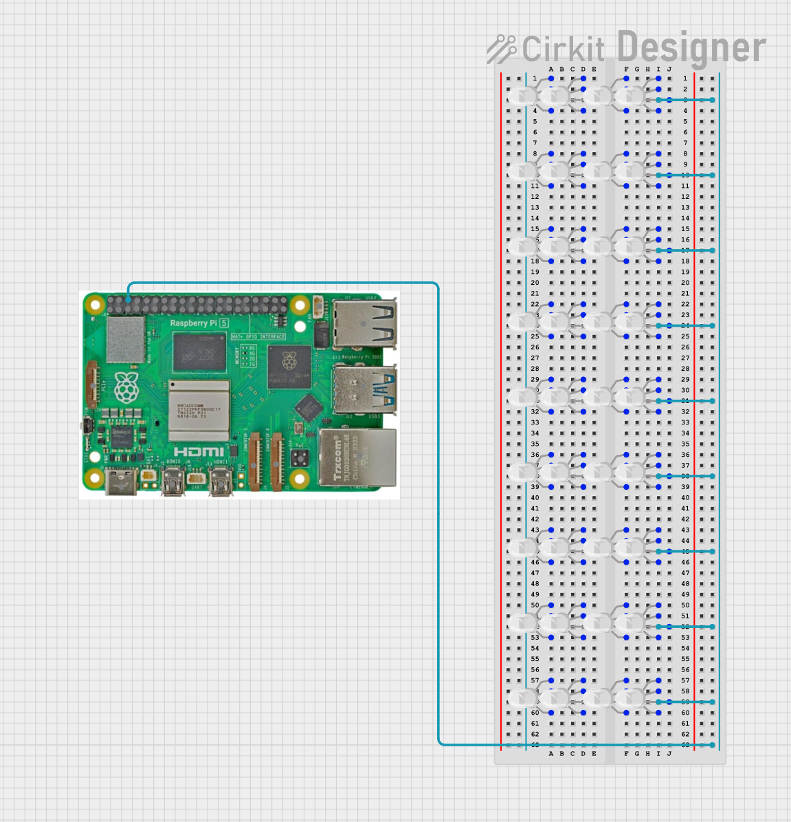
The RGB button with a common cathode configuration is a versatile electronic component that combines a tactile push button with an RGB LED. This component allows users to display multiple colors by controlling the individual anodes of the red, green, and blue LEDs. The common cathode is connected to ground, while the anodes are connected to a microcontroller or other control circuit to select and mix colors.
Explore Projects Built with rgb button common cathode
Explore Projects Built with rgb button common cathode
Common Applications and Use Cases
- User interfaces for electronic devices
- Status indicators in embedded systems
- Gaming controllers and arcade machines
- DIY electronics and hobby projects
- Educational tools for learning about LEDs and color mixing
Technical Specifications
Key Technical Details
- Operating Voltage (LEDs): Typically 2.0V (Red), 3.0V (Green), 3.0V (Blue)
- Forward Current (LEDs): 20mA (maximum per LED)
- Button Rating: 50mA at 12V DC
- Common Cathode: Connected to ground (GND)
- LED Control: Individual anodes for Red, Green, and Blue
- Button Type: Momentary push button
- Dimensions: Varies by manufacturer (e.g., 12mm diameter button cap)
Pin Configuration and Descriptions
The RGB button typically has 4 or 5 pins, depending on the design. Below is a general pinout:
| Pin Number | Label | Description |
|---|---|---|
| 1 | Cathode (GND) | Common cathode for all LEDs, connects to ground. |
| 2 | Red Anode | Controls the red LED, connects to a current-limiting resistor and control pin. |
| 3 | Green Anode | Controls the green LED, connects to a current-limiting resistor and control pin. |
| 4 | Blue Anode | Controls the blue LED, connects to a current-limiting resistor and control pin. |
| 5 (optional) | Button Output | Connects to the push button output, typically pulled high or low. |
Note: Always refer to the datasheet of your specific RGB button for exact pinout details.
Usage Instructions
How to Use the Component in a Circuit
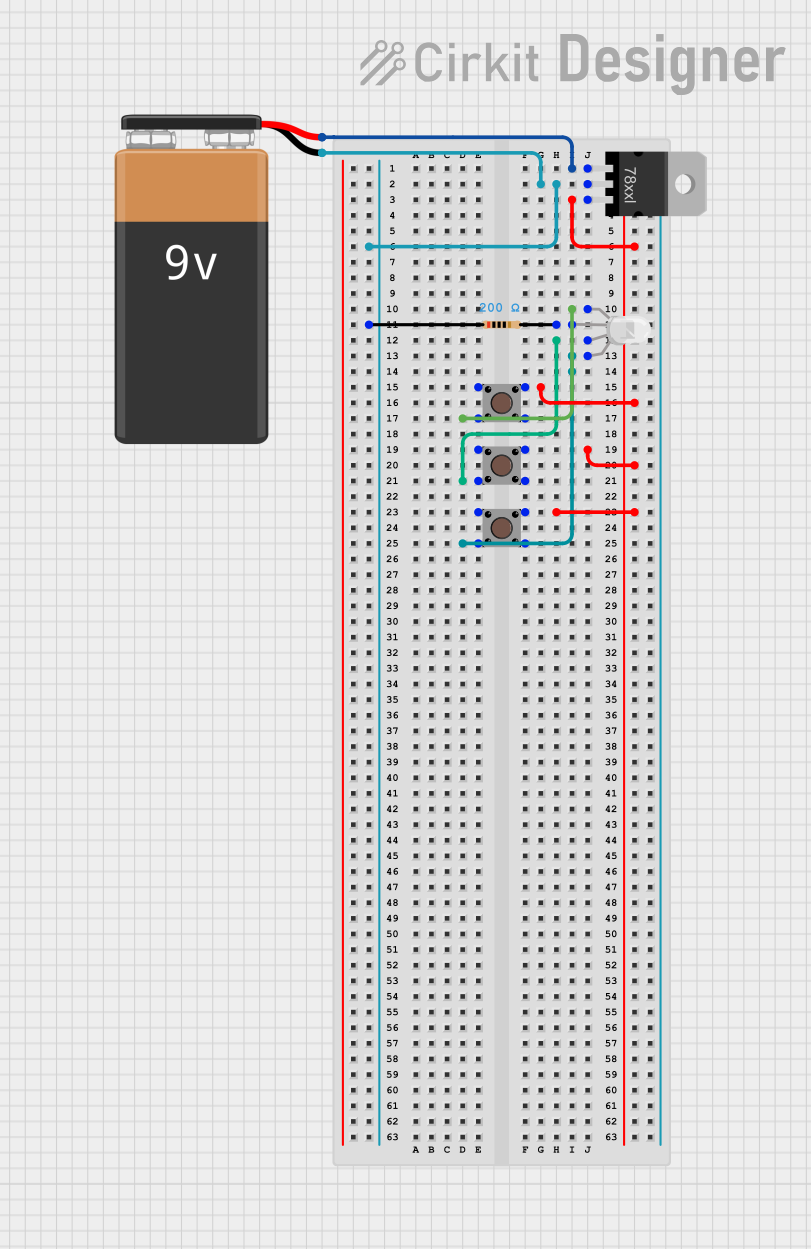
Connect the Common Cathode:
- Connect the cathode pin to the ground (GND) of your circuit.
Connect the Anodes:
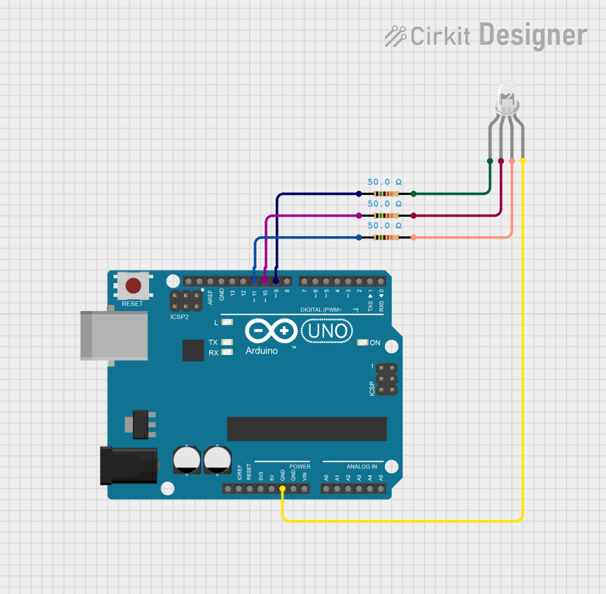
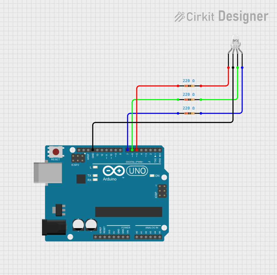
- Attach each anode (Red, Green, Blue) to a current-limiting resistor (e.g., 220Ω to 330Ω) to prevent excessive current through the LEDs.
- Connect the other end of each resistor to a microcontroller's GPIO pin or another control circuit.
Button Connection:
- If the button pin is present, connect it to a GPIO pin on your microcontroller. Use a pull-up or pull-down resistor as needed.
Control the LEDs:
- Use PWM (Pulse Width Modulation) signals on the GPIO pins to control the brightness of each LED and mix colors.
Important Considerations and Best Practices
- Current Limiting: Always use appropriate resistors to limit the current through the LEDs. Failure to do so may damage the LEDs.
- Voltage Levels: Ensure the microcontroller's GPIO pins can provide sufficient voltage and current for the LEDs.
- Debouncing the Button: If using the button for input, implement software or hardware debouncing to avoid false triggers.
- Heat Management: Avoid driving the LEDs at maximum current for extended periods to prevent overheating.
Example Code for Arduino UNO
Below is an example of how to control the RGB button with an Arduino UNO:
// Pin definitions for the RGB button
const int redPin = 9;    // Red LED anode connected to pin 9
const int greenPin = 10; // Green LED anode connected to pin 10
const int bluePin = 11;  // Blue LED anode connected to pin 11
const int buttonPin = 2; // Button output connected to pin 2

void setup() {
  // Set LED pins as outputs
  pinMode(redPin, OUTPUT);
  pinMode(greenPin, OUTPUT);
  pinMode(bluePin, OUTPUT);

  // Set button pin as input with pull-up resistor
  pinMode(buttonPin, INPUT_PULLUP);
}

void loop() {
  // Read the button state
  int buttonState = digitalRead(buttonPin);

  if (buttonState == LOW) {
    // Button is pressed, display a color (e.g., purple)
    analogWrite(redPin, 128);  // 50% brightness for red
    analogWrite(greenPin, 0);  // Green off
    analogWrite(bluePin, 128); // 50% brightness for blue
  } else {
    // Button is not pressed, turn off the LEDs
    analogWrite(redPin, 0);
    analogWrite(greenPin, 0);
    analogWrite(bluePin, 0);
  }
}
Note: Adjust the
analogWritevalues to create different colors by mixing red, green, and blue.
Troubleshooting and FAQs
Common Issues and Solutions
LEDs Not Lighting Up:
- Check the connections and ensure the cathode is connected to ground.
- Verify that the current-limiting resistors are properly connected.
- Ensure the GPIO pins are configured as outputs and providing the correct signals.
Incorrect Colors Displayed:
- Verify the anode connections to the correct GPIO pins.
- Check the PWM values in your code to ensure proper color mixing.
Button Not Responding:
- Ensure the button pin is properly connected and configured as an input.
- Check for proper pull-up or pull-down resistor configuration.
- Implement debouncing in software if the button triggers multiple times.
Flickering LEDs:
- Verify that the PWM frequency is appropriate for the LEDs.
- Check for loose connections or unstable power supply.
FAQs
Q: Can I use the RGB button without a microcontroller?
A: Yes, you can use simple switches or potentiometers to control the anodes, but a microcontroller provides more precise control over colors and brightness.
Q: What resistor value should I use for the LEDs?
A: Typically, 220Ω to 330Ω resistors are suitable, but the exact value depends on the LED's forward voltage and the supply voltage.
Q: Can I use this component with a 3.3V microcontroller?
A: Yes, but ensure the LEDs receive sufficient voltage to light up. You may need to adjust resistor values accordingly.
Q: How do I create white light with the RGB button?
A: Set all three LEDs (Red, Green, Blue) to equal brightness using PWM signals. For example, analogWrite(redPin, 255); analogWrite(greenPin, 255); analogWrite(bluePin, 255);.
By following this documentation, you can effectively integrate and troubleshoot the RGB button with a common cathode in your projects.