How to Use RS485 Waterproof Ambient Light Sensor: Examples, Pinouts, and Specs
Introduction
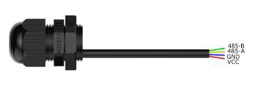
The RS485 Waterproof Ambient Light Sensor by DFRobot is a robust and reliable sensor designed to measure ambient light levels in various environments. Its waterproof design makes it ideal for outdoor applications, ensuring accurate light measurements even in harsh weather conditions. The sensor communicates using the RS485 interface, which allows for long-distance, noise-resistant data transmission, making it suitable for industrial and environmental monitoring systems.
Explore Projects Built with RS485 Waterproof Ambient Light Sensor


Explore Projects Built with RS485 Waterproof Ambient Light Sensor
Common Applications and Use Cases
- Smart street lighting systems
- Agricultural light monitoring
- Outdoor environmental monitoring
- Industrial automation
- Solar panel optimization
Technical Specifications
Below are the key technical details of the RS485 Waterproof Ambient Light Sensor:
| Parameter | Value |
|---|---|
| Operating Voltage | 5V DC |
| Communication Protocol | RS485 (Modbus RTU) |
| Measurement Range | 0 to 100,000 lux |
| Accuracy | ±5% |
| Waterproof Rating | IP65 |
| Operating Temperature | -40°C to 85°C |
| Power Consumption | < 0.5W |
| Dimensions | 60mm x 30mm x 20mm |
Pin Configuration and Descriptions
The sensor has a 4-wire interface for power and communication. The pinout is as follows:
| Pin | Color | Description |
|---|---|---|
| VCC | Red | Power supply (5V DC) |
| GND | Black | Ground |
| A | Yellow | RS485 Data Line A (D+) |
| B | Green | RS485 Data Line B (D-) |
Usage Instructions
How to Use the Component in a Circuit
- Power the Sensor: Connect the red wire (VCC) to a 5V DC power source and the black wire (GND) to ground.
- Connect RS485 Interface:
- Connect the yellow wire (A) to the RS485 Data Line A (D+).
- Connect the green wire (B) to the RS485 Data Line B (D-).
- RS485 to UART Converter: If using a microcontroller like an Arduino UNO, you will need an RS485-to-UART converter module to interface with the sensor.
- Modbus Communication: Use the Modbus RTU protocol to query the sensor for ambient light data. The sensor typically responds with the light intensity in lux.
Important Considerations and Best Practices
- Waterproofing: Ensure that the sensor is properly sealed and mounted in outdoor environments to maintain its IP65 rating.
- Cable Length: RS485 supports long cable runs, but ensure proper termination resistors are used to avoid signal reflections.
- Power Supply: Use a stable 5V DC power source to avoid measurement inaccuracies.
- Modbus Address: The default Modbus address of the sensor is typically set by the manufacturer. Refer to the product manual to confirm or change the address if needed.
Example Code for Arduino UNO
Below is an example of how to interface the RS485 Waterproof Ambient Light Sensor with an Arduino UNO using a Modbus library:
#include <ModbusMaster.h>

// Instantiate ModbusMaster object
ModbusMaster node;

// RS485 communication pins
#define RE_DE 2  // Pin to control RS485 module (RE/DE)

void preTransmission() {
  digitalWrite(RE_DE, HIGH); // Enable RS485 transmission
}

void postTransmission() {
  digitalWrite(RE_DE, LOW);  // Disable RS485 transmission
}

void setup() {
  Serial.begin(9600);        // Initialize serial communication
  pinMode(RE_DE, OUTPUT);    // Set RE/DE pin as output
  digitalWrite(RE_DE, LOW);  // Set RS485 to receive mode

  // Initialize Modbus communication
  node.begin(1, Serial);     // Modbus ID 1 (default for the sensor)
  node.preTransmission(preTransmission);
  node.postTransmission(postTransmission);
}

void loop() {
  uint8_t result;
  uint16_t lux;

  // Read ambient light data (register 0x0001)
  result = node.readInputRegisters(0x0001, 1);

  if (result == node.ku8MBSuccess) {
    lux = node.getResponseBuffer(0); // Get lux value from response
    Serial.print("Ambient Light (lux): ");
    Serial.println(lux);
  } else {
    Serial.println("Failed to read from sensor.");
  }

  delay(1000); // Wait 1 second before next reading
}
Notes on the Code
- The
ModbusMasterlibrary is used for Modbus RTU communication. Install it via the Arduino Library Manager. - Adjust the Modbus ID (
node.begin(1, Serial)) if the sensor's address is different. - Ensure the RS485 module is properly connected to the Arduino's TX and RX pins.
Troubleshooting and FAQs
Common Issues and Solutions
No Data Received from the Sensor
- Verify the RS485 connections (A and B lines) and ensure they are not swapped.
- Check the Modbus address and ensure it matches the sensor's configuration.
- Confirm that the RS485 module is powered and functioning correctly.
Inaccurate Light Measurements
- Ensure the sensor is not obstructed or covered by dirt or debris.
- Verify that the power supply is stable and within the specified voltage range.
Communication Errors
- Check for proper termination resistors (120Ω) at both ends of the RS485 bus.
- Ensure the baud rate and communication settings match the sensor's specifications.
FAQs
Q: Can I use this sensor indoors?
A: Yes, the sensor can be used indoors, but its waterproof design is optimized for outdoor environments.
Q: What is the maximum cable length supported by RS485?
A: RS485 supports cable lengths up to 1200 meters, depending on the baud rate and cable quality.
Q: How do I change the Modbus address of the sensor?
A: Refer to the manufacturer's documentation for instructions on changing the Modbus address, typically done via specific Modbus commands.
Q: Is the sensor compatible with 3.3V microcontrollers?
A: The sensor requires a 5V power supply. Use a level shifter if interfacing with a 3.3V microcontroller.
This concludes the documentation for the RS485 Waterproof Ambient Light Sensor. For further details, refer to the official DFRobot product manual.