Cirkit Designer Logo
Cirkit Designer
Your all-in-one circuit design IDE
Home / 
Component Documentation

How to Use PQ1CY1032Z: Examples, Pinouts, and Specs

Image of PQ1CY1032Z
Cirkit Designer LogoDesign with PQ1CY1032Z in Cirkit Designer

Introduction

The PQ1CY1032Z is a sophisticated electronic component that functions as a voltage-operated 2-channel relay. It integrates a low RDSON Field-Effect Transistor (FET) with a manganese-zinc (MnZn) core coil designed to absorb noise, making it an ideal choice for applications requiring reliable switching with minimal electromagnetic interference (EMI). Common applications include power management systems, automotive electronics, and industrial control circuits where precise and noise-free operation is crucial.

Explore Projects Built with PQ1CY1032Z

Use Cirkit Designer to design, explore, and prototype these projects online. Some projects support real-time simulation. Click "Open Project" to start designing instantly!
Solar-Powered STM32-Based Automation System with Matrix Keypad and RTC
Image of soloar cleaner : A project utilizing PQ1CY1032Z in a practical application
This circuit features an STM32F103C8T6 microcontroller interfaced with a membrane matrix keypad for input, an RTC DS3231 for real-time clock functionality, and a 16x2 I2C LCD for display. It controls four 12V geared motors through two MD20 CYTRON motor drivers, with the motor power supplied by a 12V battery regulated by a buck converter. The battery is charged via a solar panel connected through a solar charge controller, ensuring a renewable energy source for the system.
Cirkit Designer LogoOpen Project in Cirkit Designer
Battery-Powered Emergency Alert System with NUCLEO-F072RB, SIM800L, and GPS NEO 6M
Image of women safety: A project utilizing PQ1CY1032Z in a practical application
This circuit is an emergency alert system that uses a NUCLEO-F072RB microcontroller to send SMS alerts and make calls via a SIM800L GSM module, while obtaining location data from a GPS NEO 6M module. The system is powered by a Li-ion battery and includes a TP4056 module for battery charging and protection, with a rocker switch to control power to the microcontroller.
Cirkit Designer LogoOpen Project in Cirkit Designer
Satellite-Based Timing and Navigation System with SDR and Atomic Clock Synchronization
Image of GPS 시스템 측정 구성도_Confirm: A project utilizing PQ1CY1032Z in a practical application
This circuit appears to be a complex system involving power supply management, GPS and timing synchronization, and data communication. It includes a SI-TEX G1 Satellite Compass for GPS data, an XHTF1021 Atomic Rubidium Clock for precise timing, and Ettus USRP B200 units for software-defined radio communication. Power is supplied through various SMPS units and distributed via terminal blocks and DC jacks. Data communication is facilitated by Beelink MINI S12 N95 computers, RS232 splitters, and a 1000BASE-T Media Converter for network connectivity. RF Directional Couplers are used to interface antennas with the USRP units, and the entire system is likely contained within cases for protection and organization.
Cirkit Designer LogoOpen Project in Cirkit Designer
ESP32 Smart Socket with Energy Monitoring and OLED Display
Image of Energy Meter: A project utilizing PQ1CY1032Z in a practical application
This circuit is a smart socket for energy monitoring, utilizing an ESP32 microcontroller to read voltage and current from ZMPT101B and ACS712 sensors. The readings are displayed on a 0.96" OLED screen, and a relay module is used to control a connected load, such as a bulb, remotely. The system is powered by a 220V AC source, converted to DC by an HLK-PM01 module.
Cirkit Designer LogoOpen Project in Cirkit Designer

Explore Projects Built with PQ1CY1032Z

Use Cirkit Designer to design, explore, and prototype these projects online. Some projects support real-time simulation. Click "Open Project" to start designing instantly!
Image of soloar cleaner : A project utilizing PQ1CY1032Z in a practical application
Solar-Powered STM32-Based Automation System with Matrix Keypad and RTC
This circuit features an STM32F103C8T6 microcontroller interfaced with a membrane matrix keypad for input, an RTC DS3231 for real-time clock functionality, and a 16x2 I2C LCD for display. It controls four 12V geared motors through two MD20 CYTRON motor drivers, with the motor power supplied by a 12V battery regulated by a buck converter. The battery is charged via a solar panel connected through a solar charge controller, ensuring a renewable energy source for the system.
Cirkit Designer LogoOpen Project in Cirkit Designer
Image of women safety: A project utilizing PQ1CY1032Z in a practical application
Battery-Powered Emergency Alert System with NUCLEO-F072RB, SIM800L, and GPS NEO 6M
This circuit is an emergency alert system that uses a NUCLEO-F072RB microcontroller to send SMS alerts and make calls via a SIM800L GSM module, while obtaining location data from a GPS NEO 6M module. The system is powered by a Li-ion battery and includes a TP4056 module for battery charging and protection, with a rocker switch to control power to the microcontroller.
Cirkit Designer LogoOpen Project in Cirkit Designer
Image of GPS 시스템 측정 구성도_Confirm: A project utilizing PQ1CY1032Z in a practical application
Satellite-Based Timing and Navigation System with SDR and Atomic Clock Synchronization
This circuit appears to be a complex system involving power supply management, GPS and timing synchronization, and data communication. It includes a SI-TEX G1 Satellite Compass for GPS data, an XHTF1021 Atomic Rubidium Clock for precise timing, and Ettus USRP B200 units for software-defined radio communication. Power is supplied through various SMPS units and distributed via terminal blocks and DC jacks. Data communication is facilitated by Beelink MINI S12 N95 computers, RS232 splitters, and a 1000BASE-T Media Converter for network connectivity. RF Directional Couplers are used to interface antennas with the USRP units, and the entire system is likely contained within cases for protection and organization.
Cirkit Designer LogoOpen Project in Cirkit Designer
Image of Energy Meter: A project utilizing PQ1CY1032Z in a practical application
ESP32 Smart Socket with Energy Monitoring and OLED Display
This circuit is a smart socket for energy monitoring, utilizing an ESP32 microcontroller to read voltage and current from ZMPT101B and ACS712 sensors. The readings are displayed on a 0.96" OLED screen, and a relay module is used to control a connected load, such as a bulb, remotely. The system is powered by a 220V AC source, converted to DC by an HLK-PM01 module.
Cirkit Designer LogoOpen Project in Cirkit Designer

Technical Specifications

Key Technical Details

  • Operating Voltage Range: 3.0V to 5.5V
  • Control Input Voltage: 0V to VDD
  • Continuous Load Current: Up to 2A per channel
  • On-Resistance (RDSON): Typically 70 mΩ at 25°C
  • Switching Speed: Fast turn-on and turn-off times
  • Operating Temperature Range: -40°C to +85°C

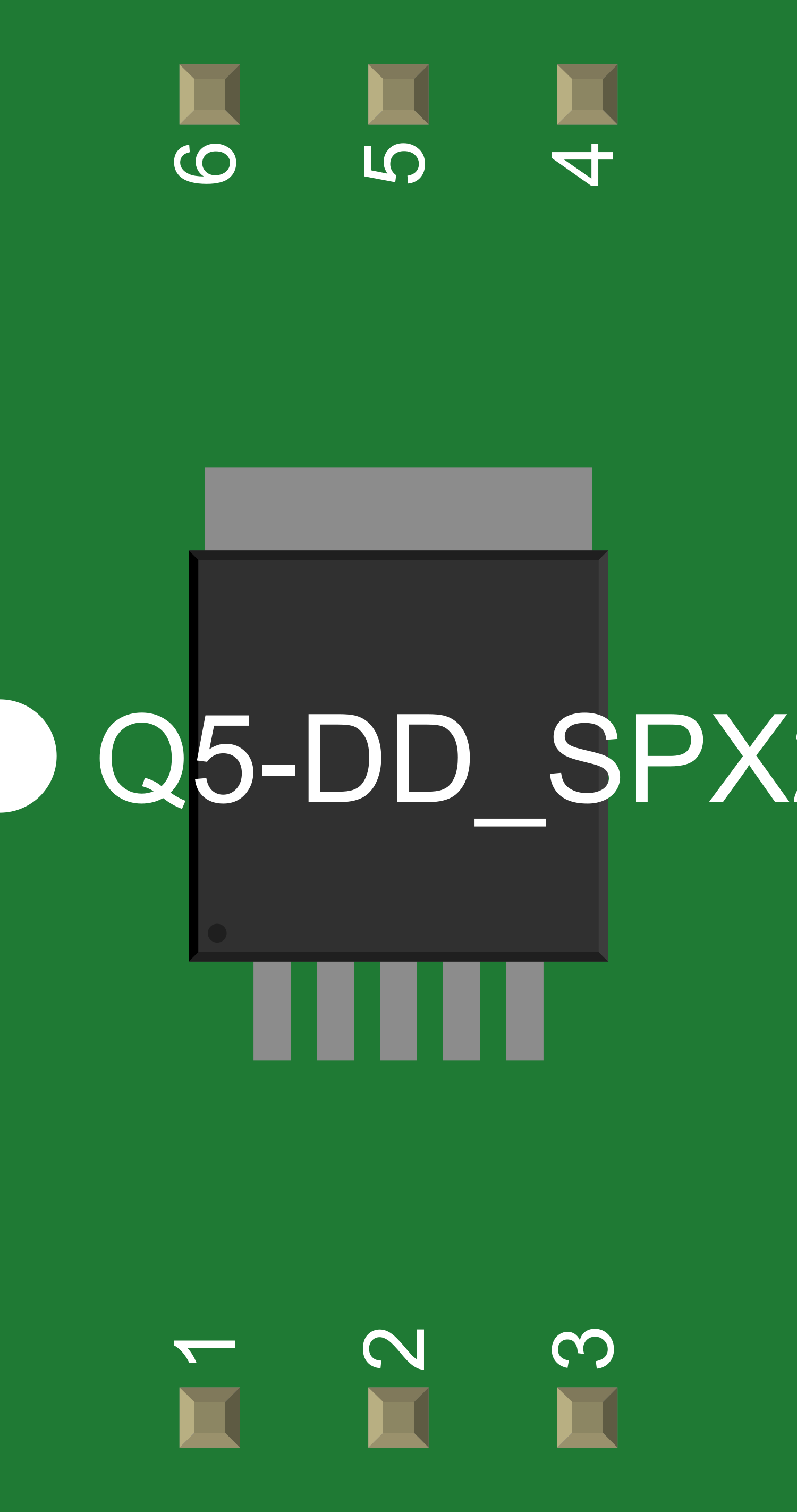
Pin Configuration and Descriptions

Pin Number Pin Name Description
1 IN1 Control input for channel 1
2 GND Ground connection
3 OUT1 Output for channel 1
4 VDD Power supply input
5 OUT2 Output for channel 2
6 IN2 Control input for channel 2

Usage Instructions

How to Use the Component in a Circuit

  1. Power Supply Connection: Connect the VDD pin to a stable power supply within the operating voltage range.
  2. Ground Connection: Connect the GND pin to the system ground.
  3. Control Inputs: Apply a control voltage to IN1 and IN2 to switch the respective channels. Ensure that the control voltage does not exceed VDD.
  4. Load Connection: Connect the load to the OUT1 and OUT2 pins. Ensure that the load current does not exceed the specified continuous load current rating.

Important Considerations and Best Practices

  • Decoupling Capacitors: Place a decoupling capacitor close to the VDD pin to stabilize the power supply and minimize voltage spikes.
  • Heat Dissipation: Ensure adequate heat dissipation if the relay operates near its maximum current rating to prevent overheating.
  • Protection Diodes: Use protection diodes across inductive loads to prevent voltage spikes during switching.
  • EMI Considerations: Take advantage of the built-in noise-absorbing coil for applications sensitive to EMI.

Troubleshooting and FAQs

Common Issues

  • Relay Not Switching: Ensure that the control voltage is within the specified range and that the power supply is connected properly.
  • Overheating: Check if the load current exceeds the maximum rating or improve heat dissipation.

Solutions and Tips for Troubleshooting

  • Verify Connections: Double-check all connections, including power supply, ground, and control inputs.
  • Measure Voltages: Use a multimeter to measure the control input voltage and the power supply voltage to ensure they are within specifications.
  • Load Testing: Test the relay with a lower current load to rule out issues with the load itself.

FAQs

Q: Can the PQ1CY1032Z be used with an Arduino UNO? A: Yes, the relay can be controlled using the digital output pins of an Arduino UNO.

Q: Is it necessary to use a current limiting resistor with the control inputs? A: It depends on the control voltage source. If the voltage exceeds the VDD, a current limiting resistor may be required.

Example Code for Arduino UNO

// Define control pins for the relay channels
const int relayChannel1 = 2; // IN1 connected to digital pin 2
const int relayChannel2 = 3; // IN2 connected to digital pin 3

void setup() {
  // Set the relay control pins as outputs
  pinMode(relayChannel1, OUTPUT);
  pinMode(relayChannel2, OUTPUT);
}

void loop() {
  // Turn on channel 1
  digitalWrite(relayChannel1, HIGH);
  delay(1000); // Wait for 1 second
  
  // Turn off channel 1
  digitalWrite(relayChannel1, LOW);
  delay(1000); // Wait for 1 second
  
  // Turn on channel 2
  digitalWrite(relayChannel2, HIGH);
  delay(1000); // Wait for 1 second
  
  // Turn off channel 2
  digitalWrite(relayChannel2, LOW);
  delay(1000); // Wait for 1 second
}

This example demonstrates how to control the PQ1CY1032Z using an Arduino UNO. The relay channels are turned on and off alternately with a one-second interval between each action. Ensure that the VDD pin of the relay is connected to a suitable power supply and the GND pin is connected to the Arduino's ground.