How to Use Magnetic Contactor: Examples, Pinouts, and Specs
Introduction
A magnetic contactor, part ID MC_01, manufactured by Custom, is an electrically controlled switch designed for switching power circuits. Unlike standard relays, magnetic contactors are specifically engineered to handle higher current applications, making them ideal for industrial and commercial use. The device operates using an electromagnet that, when energized, closes the contacts to allow current to flow through the circuit.
Explore Projects Built with Magnetic Contactor


Explore Projects Built with Magnetic Contactor
Common Applications and Use Cases
- Motor control in industrial machinery
- HVAC systems for controlling compressors and fans
- Lighting systems in commercial buildings
- Power distribution and automation systems
- Conveyor belt systems and other high-power equipment
Technical Specifications
Key Technical Details
| Parameter | Value |
|---|---|
| Manufacturer | Custom |
| Part ID | MC_01 |
| Rated Operating Voltage | 24V DC (coil voltage) |
| Contact Voltage Rating | Up to 600V AC |
| Contact Current Rating | Up to 50A |
| Number of Poles | 3 (Three-phase) |
| Coil Power Consumption | 5W |
| Mechanical Life | 10 million operations |
| Electrical Life | 1 million operations |
| Operating Temperature | -20°C to 60°C |
| Mounting Type | DIN rail or panel mount |
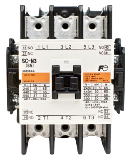
Pin Configuration and Descriptions
| Pin/Terminal Label | Description |
|---|---|
| L1, L2, L3 | Input terminals for the three-phase power supply |
| T1, T2, T3 | Output terminals for the load connection |
| A1, A2 | Coil terminals for energizing the contactor |
| NO (Normally Open) | Auxiliary contact for control circuit (optional) |
| NC (Normally Closed) | Auxiliary contact for control circuit (optional) |
Usage Instructions
How to Use the Magnetic Contactor in a Circuit
Power Supply Connection:
- Connect the three-phase power supply to the input terminals labeled L1, L2, L3.
- Ensure the voltage and current ratings of the power supply match the contactor's specifications.
Load Connection:
- Connect the load (e.g., motor, lighting system) to the output terminals labeled T1, T2, T3.
- Verify that the load's current and voltage requirements are within the contactor's rated capacity.
Coil Connection:
- Connect the control voltage (e.g., 24V DC) to the coil terminals A1 and A2.
- Use a switch or control circuit to energize the coil and activate the contactor.
Auxiliary Contacts (Optional):
- Use the auxiliary contacts (NO or NC) for additional control or feedback in the circuit.
Important Considerations and Best Practices
- Overload Protection: Always use an appropriate overload relay in series with the contactor to protect the load from overcurrent conditions.
- Wiring: Ensure all connections are secure and use appropriately rated wires for the current and voltage.
- Mounting: Install the contactor on a DIN rail or panel mount in a well-ventilated enclosure to prevent overheating.
- Noise Suppression: For DC coils, consider adding a flyback diode across the coil terminals to suppress voltage spikes when the coil is de-energized.
- Testing: Before connecting the load, test the contactor operation by energizing the coil and verifying the contact closure.
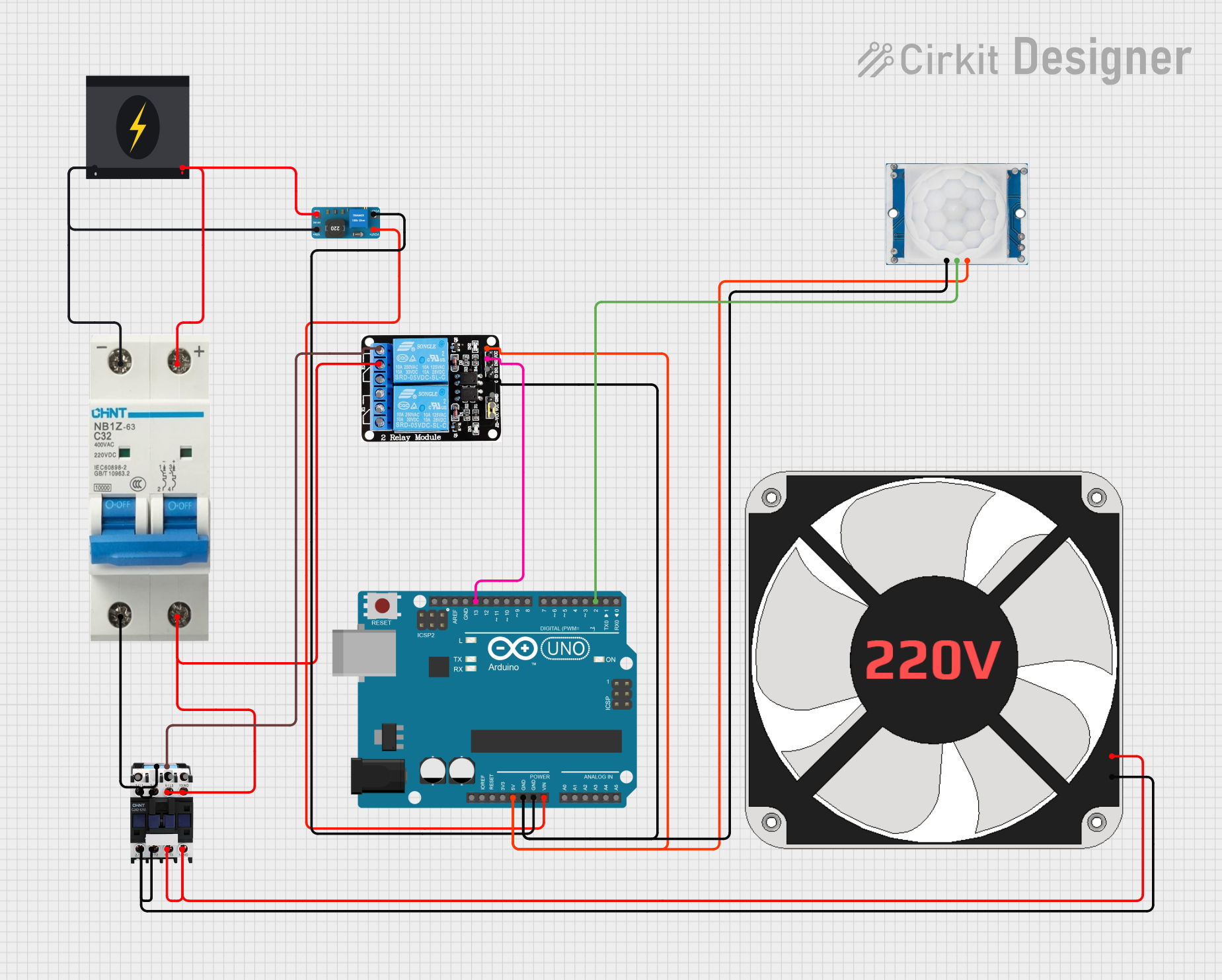
Example: Controlling a Motor with Arduino UNO
Below is an example of how to control the magnetic contactor using an Arduino UNO:
// Magnetic Contactor Control with Arduino UNO
// This example demonstrates how to use a digital pin to control the contactor coil.

const int contactorPin = 7; // Pin connected to the contactor coil (via a relay or transistor)

void setup() {
  pinMode(contactorPin, OUTPUT); // Set the pin as an output
  digitalWrite(contactorPin, LOW); // Ensure the contactor is off initially
}

void loop() {
  // Turn the contactor ON
  digitalWrite(contactorPin, HIGH);
  delay(5000); // Keep the contactor ON for 5 seconds

  // Turn the contactor OFF
  digitalWrite(contactorPin, LOW);
  delay(5000); // Keep the contactor OFF for 5 seconds
}
Note: Use a relay module or transistor circuit to interface the Arduino with the contactor coil, as the Arduino cannot directly drive the coil due to its current limitations.
Troubleshooting and FAQs
Common Issues and Solutions
Contactor Does Not Energize:
- Cause: No control voltage at the coil terminals.
- Solution: Check the control circuit and ensure the correct voltage is applied to A1 and A2.
Contacts Do Not Close Even When Coil is Energized:
- Cause: Mechanical failure or worn-out contacts.
- Solution: Inspect the contactor for physical damage and replace it if necessary.
Excessive Noise During Operation:
- Cause: Loose mounting or improper coil voltage.
- Solution: Tighten the mounting screws and verify the coil voltage matches the specifications.
Overheating:
- Cause: Overcurrent or poor ventilation.
- Solution: Ensure the load current is within the rated capacity and improve ventilation around the contactor.
FAQs
Q: Can I use the MC_01 contactor for single-phase applications?
A: Yes, you can use it for single-phase applications by connecting only one pair of input and output terminals (e.g., L1 to T1).Q: What is the purpose of the auxiliary contacts?
A: Auxiliary contacts are used for control or feedback purposes, such as signaling the contactor's status to a control system.Q: How do I know when to replace the contactor?
A: Replace the contactor if you notice excessive wear on the contacts, frequent failures to energize, or if it has reached its rated mechanical or electrical life.Q: Can I mount the contactor in any orientation?
A: It is recommended to mount the contactor vertically for optimal performance and longevity.