
How to Use Header 5x2: Examples, Pinouts, and Specs
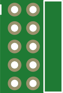
 Design with Header 5x2 in Cirkit Designer
Introduction
A 5x2 header is a type of connector with 10 pins arranged in two rows of 5 pins each. It is commonly used in electronics for creating reliable and detachable connections between circuit boards, wires, or other components. These headers are often paired with matching female connectors or ribbon cables, enabling easy plug-and-play functionality.
Explore Projects Built with Header 5x2
 Open Project in Cirkit Designer
 Open Project in Cirkit Designer
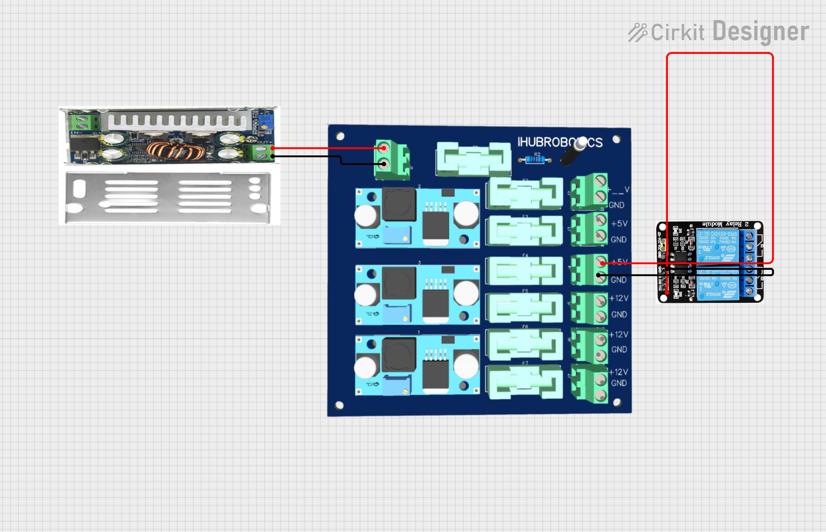 Open Project in Cirkit Designer
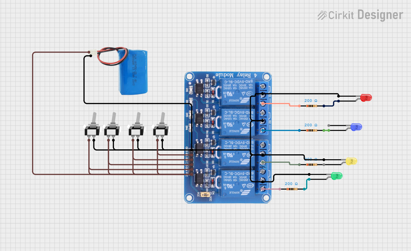 Open Project in Cirkit Designer
Explore Projects Built with Header 5x2
Open Project in Cirkit DesignerOpen Project in Cirkit DesignerOpen Project in Cirkit DesignerOpen Project in Cirkit DesignerCommon Applications:
- Microcontroller programming interfaces (e.g., ISP headers)
- Connecting peripherals like displays, sensors, or modules
- Debugging and testing circuits
- Power and signal distribution in compact designs
Technical Specifications
Key Technical Details:
- Pin Count: 10 (arranged in 2 rows of 5 pins)
- Pin Pitch: 2.54 mm (standard spacing)
- Current Rating: Typically 1A per pin (varies by manufacturer)
- Voltage Rating: Up to 250V (varies by manufacturer)
- Material: Gold-plated or tin-plated brass pins, plastic insulator
- Temperature Range: -40°C to 105°C (typical)
Pin Configuration and Descriptions:
The pin configuration of a 5x2 header depends on its application. Below is an example of a common pinout for an ISP (In-System Programming) header used with microcontrollers:
| Pin Number | Row | Description |
|---|---|---|
| 1 | 1 | MISO (Master In Slave Out) |
| 2 | 2 | VCC (Power Supply) |
| 3 | 1 | SCK (Serial Clock) |
| 4 | 2 | MOSI (Master Out Slave In) |
| 5 | 1 | RESET (Reset Signal) |
| 6 | 2 | GND (Ground) |
| 7 | 1 | NC (Not Connected) |
| 8 | 2 | NC (Not Connected) |
| 9 | 1 | NC (Not Connected) |
| 10 | 2 | NC (Not Connected) |
Note: The pinout may vary depending on the specific application or manufacturer. Always refer to the datasheet or schematic for your specific use case.
Usage Instructions
How to Use the Header 5x2 in a Circuit:
Soldering the Header:
- Align the header pins with the holes on the PCB.
- Solder each pin carefully to ensure a solid electrical connection.
- Avoid applying excessive heat to prevent damage to the plastic insulator.
Connecting Components:
- Use a matching 5x2 female connector or ribbon cable to connect to the header.
- Ensure proper alignment of the connector to avoid reversed connections.
Power and Signal Considerations:
- Verify the voltage and current ratings of the header match your circuit requirements.
- Use appropriate decoupling capacitors near the header if it carries power signals.
Example with Arduino UNO:
- A 5x2 header can be used as an ISP connector for programming an Arduino UNO. Below is an example of Arduino code to blink an LED after programming via the ISP header:
/* Example: Blink an LED using Arduino UNO
   This code assumes the microcontroller is programmed via the 5x2 ISP header.
   Ensure the LED is connected to pin 13 with a suitable resistor. */

void setup() {
  pinMode(13, OUTPUT); // Set pin 13 as an output
}

void loop() {
  digitalWrite(13, HIGH); // Turn the LED on
  delay(1000);            // Wait for 1 second
  digitalWrite(13, LOW);  // Turn the LED off
  delay(1000);            // Wait for 1 second
}
Best Practices:
- Double-check the orientation of the header and connector to avoid reversed connections.
- Use heat shrink tubing or insulation to protect exposed pins if necessary.
- For high-frequency signals, minimize the length of the connecting wires to reduce noise.
Troubleshooting and FAQs
Common Issues:
Loose Connections:
- Cause: Poor soldering or mismatched connectors.
- Solution: Re-solder the header pins or use a compatible female connector.
Reversed Connections:
- Cause: Incorrect alignment of the connector.
- Solution: Verify the pinout and ensure proper orientation before connecting.
Signal Interference:
- Cause: Long wires or improper grounding.
- Solution: Use shorter wires and ensure a solid ground connection.
Damaged Pins:
- Cause: Excessive force or repeated connections.
- Solution: Replace the header if pins are bent or broken.
FAQs:
Q: Can I use a 5x2 header for power distribution?
A: Yes, but ensure the current does not exceed the header's rating (typically 1A per pin). Use multiple pins for higher currents.
Q: How do I identify pin 1 on the header?
A: Pin 1 is usually marked with a square pad on the PCB or a notch on the plastic insulator.
Q: Can I use a 5x2 header for high-speed signals?
A: Yes, but ensure proper impedance matching and minimize wire lengths to reduce signal degradation.
Q: Are 5x2 headers compatible with breadboards?
A: No, the dual-row configuration is not breadboard-friendly. Use a breakout board or adapter for breadboard use.
By following this documentation, you can effectively integrate a 5x2 header into your electronic projects!