How to Use i2c Hub: Examples, Pinouts, and Specs
Introduction
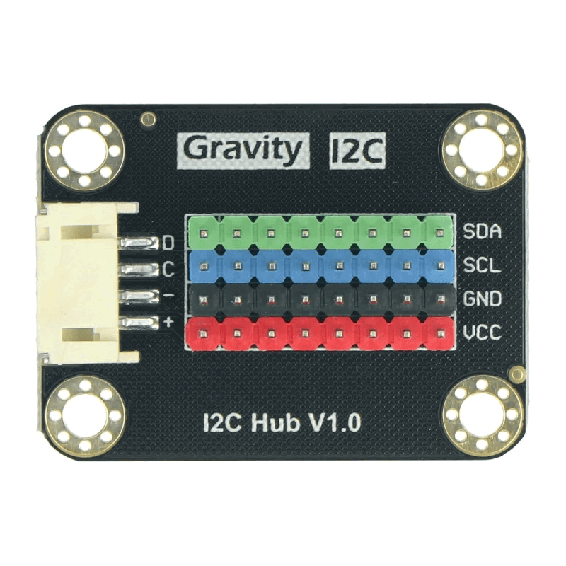
The Gravity I2C Hub (DFR0759) is a versatile device designed to facilitate the connection of multiple I2C devices to a single I2C bus. This hub simplifies the process of expanding the number of I2C peripherals that can be connected to a microcontroller, such as an Arduino UNO, by providing multiple I2C ports. This is particularly useful in complex projects where multiple sensors, displays, and other I2C devices need to communicate with the microcontroller simultaneously.
Explore Projects Built with i2c Hub
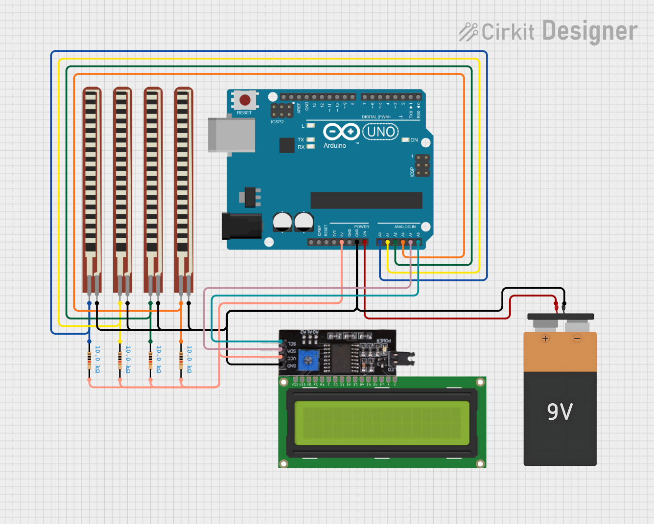
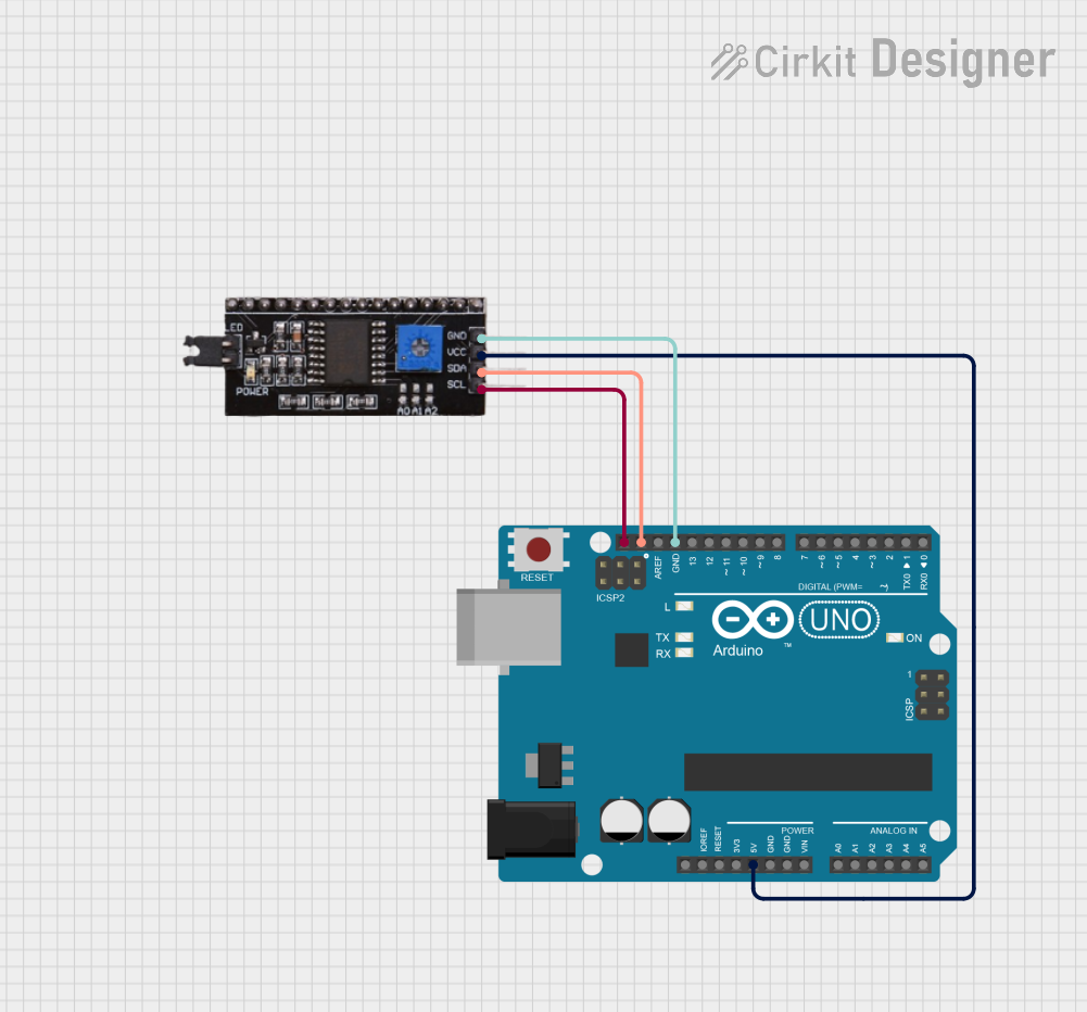

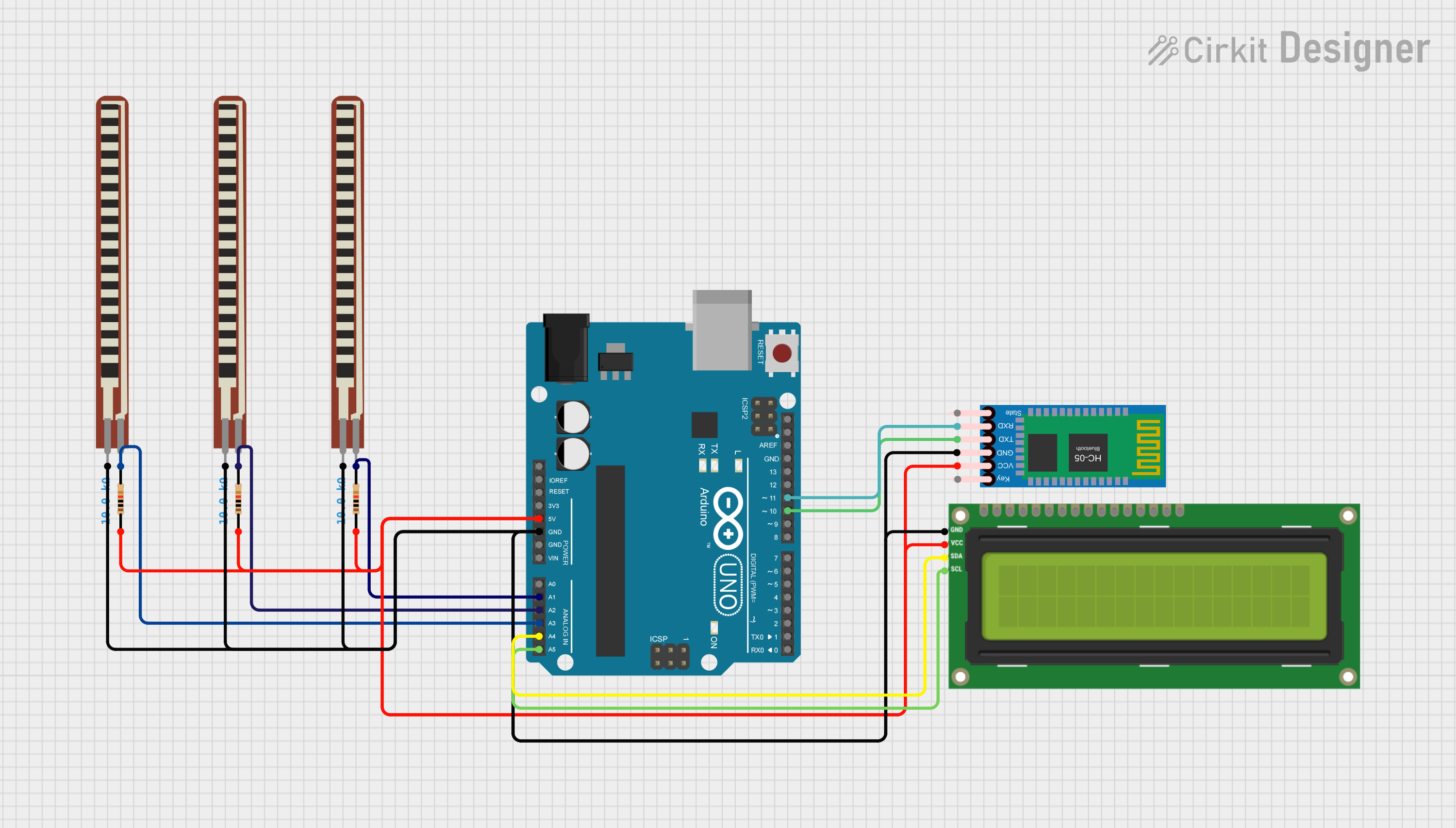
Explore Projects Built with i2c Hub
Common Applications and Use Cases
- Robotics: Connecting multiple sensors (e.g., gyroscopes, accelerometers) to a single microcontroller.
- Home Automation: Integrating various I2C-based sensors and actuators for smart home systems.
- Wearable Technology: Managing multiple I2C devices in compact, wearable electronics.
- Educational Projects: Simplifying the setup for students learning about I2C communication.
Technical Specifications
Key Technical Details
| Parameter | Value |
|---|---|
| Operating Voltage | 3.3V / 5V |
| Maximum Current | 1A |
| I2C Ports | 6 (1 input, 5 output) |
| Communication Speed | Up to 400kHz (I2C Fast Mode) |
| Dimensions | 42mm x 32mm |
Pin Configuration and Descriptions
| Pin Number | Pin Name | Description |
|---|---|---|
| 1 | VCC | Power supply (3.3V or 5V) |
| 2 | GND | Ground |
| 3 | SDA | I2C data line (shared across all ports) |
| 4 | SCL | I2C clock line (shared across all ports) |
| 5 | SDA1 | I2C data line for output port 1 |
| 6 | SCL1 | I2C clock line for output port 1 |
| 7 | SDA2 | I2C data line for output port 2 |
| 8 | SCL2 | I2C clock line for output port 2 |
| 9 | SDA3 | I2C data line for output port 3 |
| 10 | SCL3 | I2C clock line for output port 3 |
| 11 | SDA4 | I2C data line for output port 4 |
| 12 | SCL4 | I2C clock line for output port 4 |
| 13 | SDA5 | I2C data line for output port 5 |
| 14 | SCL5 | I2C clock line for output port 5 |
Usage Instructions
How to Use the Component in a Circuit
Power Connection:
- Connect the VCC pin to the 3.3V or 5V power supply of your microcontroller.
- Connect the GND pin to the ground of your microcontroller.
I2C Bus Connection:
- Connect the SDA and SCL pins of the I2C Hub to the corresponding SDA and SCL pins on your microcontroller.
Connecting I2C Devices:
- Connect the SDA and SCL lines of your I2C devices to any of the output ports (SDA1/SCL1 to SDA5/SCL5) on the I2C Hub.
Important Considerations and Best Practices
- Pull-up Resistors: Ensure that appropriate pull-up resistors are used on the SDA and SCL lines. Some microcontrollers have built-in pull-up resistors, but external resistors (typically 4.7kΩ) may be required for reliable communication.
- Address Conflicts: Each I2C device must have a unique address. Check the datasheets of your I2C devices to avoid address conflicts.
- Cable Length: Keep the I2C bus lines as short as possible to minimize signal degradation and interference.
Example Code for Arduino UNO
#include <Wire.h>

void setup() {
  Wire.begin(); // Initialize the I2C bus
  Serial.begin(9600); // Initialize serial communication for debugging
}

void loop() {
  Wire.beginTransmission(0x68); // Address of the I2C device
  Wire.write(0x00); // Register to read from
  Wire.endTransmission();

  Wire.requestFrom(0x68, 1); // Request 1 byte from the device

  if (Wire.available()) {
    int data = Wire.read(); // Read the data
    Serial.print("Data: ");
    Serial.println(data); // Print the data to the serial monitor
  }

  delay(1000); // Wait for 1 second before the next read
}
Troubleshooting and FAQs
Common Issues Users Might Face
No Communication with I2C Devices:
- Solution: Check the connections and ensure that the SDA and SCL lines are correctly connected. Verify that the I2C addresses are correct and that there are no address conflicts.
Unstable Data Readings:
- Solution: Ensure that pull-up resistors are used on the SDA and SCL lines. Check for loose connections and minimize the length of the I2C bus lines.
Power Issues:
- Solution: Verify that the VCC and GND connections are secure. Ensure that the power supply voltage matches the requirements of the I2C Hub and connected devices.
FAQs
Q: Can I use the I2C Hub with a 3.3V microcontroller?
- A: Yes, the I2C Hub is compatible with both 3.3V and 5V microcontrollers.
Q: How many I2C devices can I connect to the I2C Hub?
- A: You can connect up to 5 I2C devices to the I2C Hub.
Q: Do I need to add pull-up resistors to each I2C device?
- A: No, you only need pull-up resistors on the main SDA and SCL lines. However, ensure that the total pull-up resistance is appropriate for the bus.
By following this documentation, users can effectively integrate the Gravity I2C Hub (DFR0759) into their projects, enabling seamless communication between multiple I2C devices and their microcontroller.