How to Use FLIPSKY Mini V6 MK5: Examples, Pinouts, and Specs
Introduction
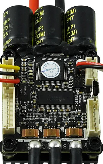
The FLIPSKY Mini V6 MK5 is a compact and powerful electronic speed controller (ESC) designed for brushless motors. Manufactured by Flipsky, this ESC is ideal for high-performance applications such as electric skateboards, scooters, robotics, and other personal electric vehicles. It features advanced firmware that ensures smooth throttle response, precise motor control, and customizable settings to suit a wide range of user needs.
Explore Projects Built with FLIPSKY Mini V6 MK5
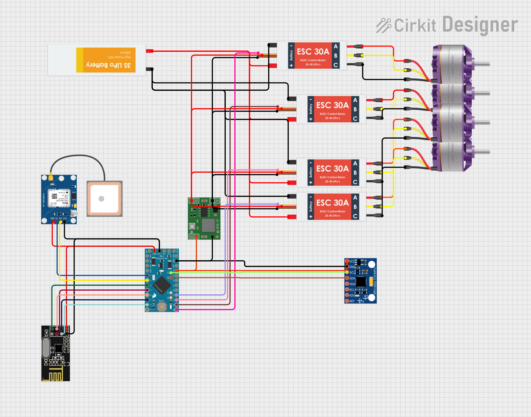
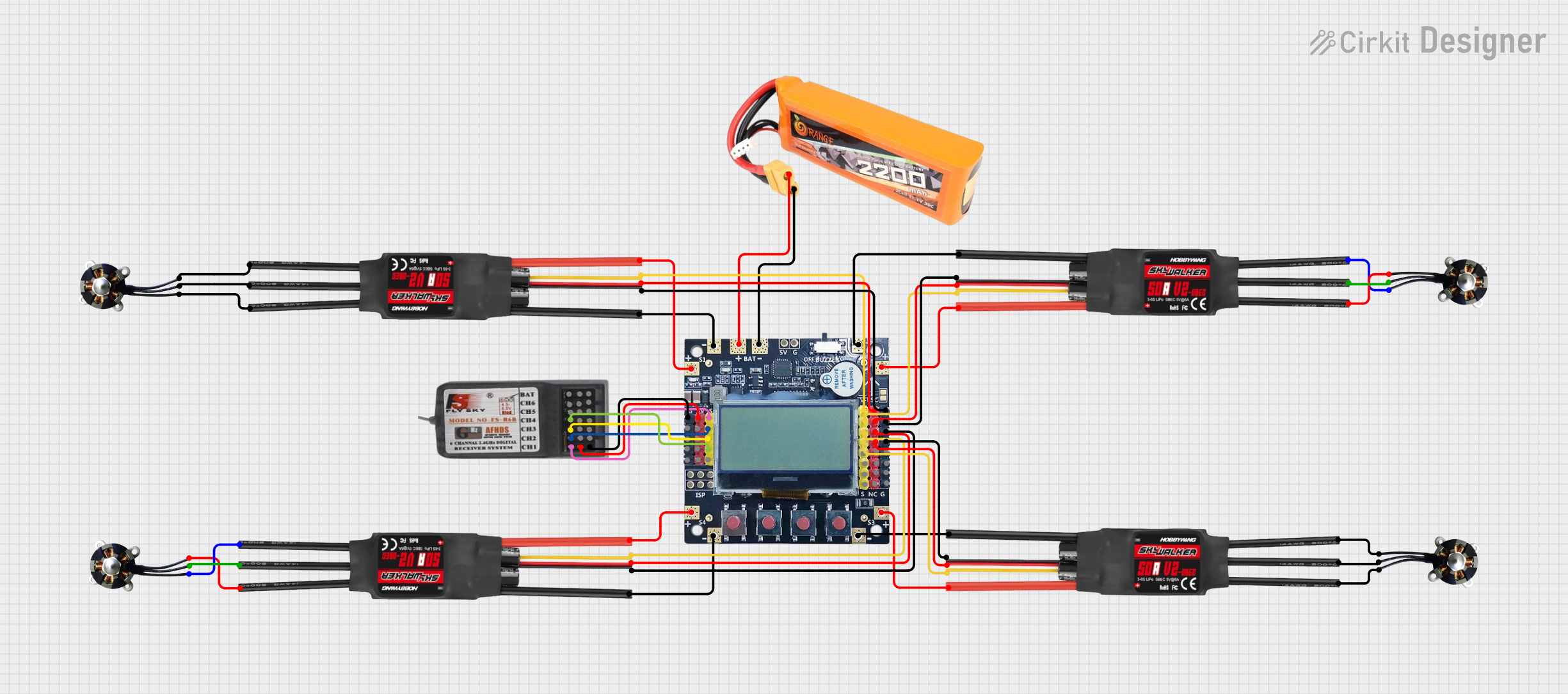
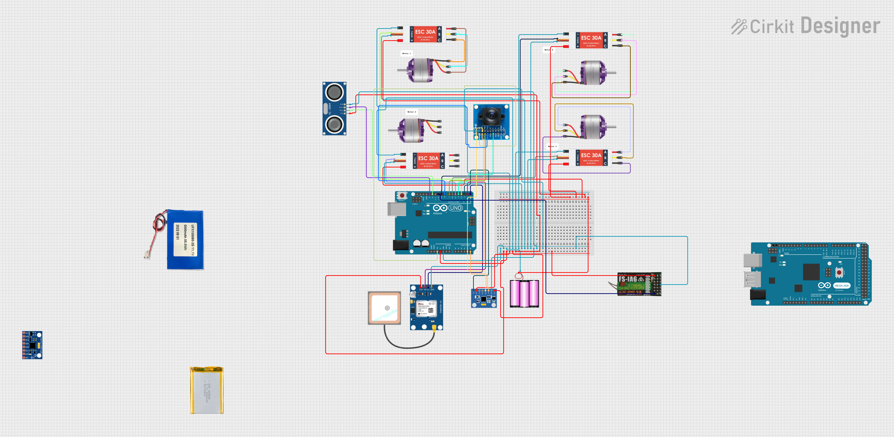
Explore Projects Built with FLIPSKY Mini V6 MK5
Common Applications
- Electric skateboards and longboards
- Electric scooters
- Robotics and automation systems
- DIY personal electric vehicles
- Remote-controlled (RC) vehicles
Technical Specifications
The FLIPSKY Mini V6 MK5 is engineered to deliver high performance in a compact form factor. Below are its key technical details:
Key Specifications
| Parameter | Value |
|---|---|
| Input Voltage Range | 8V - 60V (2S - 12S LiPo) |
| Continuous Current | 50A |
| Peak Current | 240A |
| Supported Motor Types | Brushless DC (BLDC) / FOC |
| Firmware | VESC-based |
| Communication Interfaces | UART, CAN, PPM, PWM |
| Dimensions | 65mm x 40mm x 20mm |
| Weight | 80g |
| Cooling | Passive (heatsink included) |
Pin Configuration and Descriptions
The Mini V6 MK5 features multiple connectors for motor control, power input, and communication. Below is the pin configuration:
Power and Motor Connections
| Pin Name | Description |
|---|---|
| + (Positive) | Positive terminal for battery input (8V-60V) |
| - (Negative) | Negative terminal for battery input |
| M1, M2, M3 | Motor phase connections |
Signal and Communication Ports
| Pin Name | Description |
|---|---|
| PPM/PWM | Input for throttle signal (e.g., remote) |
| UART | Serial communication interface |
| CAN_H, CAN_L | CAN bus communication lines |
| 5V | 5V output for external devices |
| GND | Ground connection |
Usage Instructions
The FLIPSKY Mini V6 MK5 is versatile and easy to integrate into various projects. Follow these steps and best practices to ensure optimal performance:
Step 1: Wiring the ESC
- Connect the Power Supply: Attach the battery's positive and negative terminals to the ESC's
+and-pins, respectively. Ensure the voltage is within the 8V-60V range. - Connect the Motor: Attach the three motor phase wires to the
M1,M2, andM3terminals. The order of connection determines motor direction, which can be adjusted later in software. - Connect the Signal Input: Use the
PPM/PWMport for throttle input from a remote receiver or microcontroller. - Optional Connections: Use the
UARTorCANports for advanced communication and configuration.
Step 2: Configuring the ESC
- Download the VESC Tool software from the Flipsky website.
- Connect the ESC to your computer via a USB-to-UART adapter.
- Open the VESC Tool and follow the on-screen instructions to:
- Detect motor parameters.
- Configure throttle response.
- Set safety limits (e.g., current, voltage).
Step 3: Testing the Setup
- Power on the system and ensure all connections are secure.
- Gradually increase the throttle to test motor response.
- Monitor the ESC temperature and current draw during operation.
Best Practices
- Use a heatsink or active cooling for prolonged high-current operation.
- Ensure proper insulation of wires to prevent short circuits.
- Regularly update the firmware for improved performance and features.
Arduino UNO Example Code
The Mini V6 MK5 can be controlled via UART using an Arduino UNO. Below is an example code snippet to send throttle commands:
#include <SoftwareSerial.h>

// Define RX and TX pins for UART communication
SoftwareSerial ESCSerial(10, 11); // RX = Pin 10, TX = Pin 11

void setup() {
  // Initialize serial communication
  ESCSerial.begin(115200); // Set baud rate to match ESC
  Serial.begin(9600);      // For debugging

  Serial.println("ESC Communication Initialized");
}

void loop() {
  // Example throttle command (adjust as needed)
  int throttleValue = 1500; // Throttle value (e.g., 1500 for neutral)

  // Send throttle command to ESC
  ESCSerial.write(throttleValue >> 8);  // Send high byte
  ESCSerial.write(throttleValue & 0xFF); // Send low byte

  // Debug output
  Serial.print("Throttle Command Sent: ");
  Serial.println(throttleValue);

  delay(100); // Delay for stability
}
Notes:
- Ensure the ESC is configured to accept UART commands.
- Adjust the
throttleValueto control motor speed (range depends on ESC settings).
Troubleshooting and FAQs
Common Issues and Solutions
Motor Does Not Spin
- Cause: Incorrect wiring or configuration.
- Solution: Verify motor phase connections and run motor detection in the VESC Tool.
ESC Overheats
- Cause: Prolonged high-current operation without adequate cooling.
- Solution: Add a heatsink or active cooling (e.g., a fan).
No Communication with VESC Tool
- Cause: Incorrect UART connection or driver issue.
- Solution: Check the USB-to-UART adapter and ensure drivers are installed.
Throttle Response is Erratic
- Cause: Misconfigured throttle input or signal interference.
- Solution: Recalibrate the throttle input in the VESC Tool.
FAQs
Can I use the Mini V6 MK5 with a 6S LiPo battery?
- Yes, the ESC supports 2S to 12S LiPo batteries, including 6S.
What is the maximum motor power supported?
- The ESC can handle up to 50A continuous current, which translates to approximately 3000W at 60V.
Is the firmware open-source?
- Yes, the Mini V6 MK5 uses VESC-based firmware, which is open-source and highly customizable.
Can I control the ESC with a Raspberry Pi?
- Yes, the ESC supports UART and CAN communication, which can be interfaced with a Raspberry Pi.
By following this documentation, users can effectively integrate and operate the FLIPSKY Mini V6 MK5 in their projects.