How to Use MAX98375: Examples, Pinouts, and Specs
Introduction
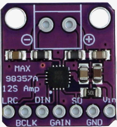
The MAX98375 is a high-efficiency, Class D audio amplifier designed for driving speakers in portable and battery-powered applications. Manufactured in China, this component integrates a digital-to-analog converter (DAC) and supports I2S audio input, making it ideal for modern audio processing tasks. Its compact design and low power consumption make it a popular choice for devices such as smartphones, tablets, portable speakers, and other audio-enabled gadgets.
Explore Projects Built with MAX98375


Explore Projects Built with MAX98375
Common Applications
- Portable Bluetooth speakers
- Smartphones and tablets
- Wearable devices
- Smart home audio systems
- Battery-powered audio devices
Technical Specifications
Key Technical Details
| Parameter | Value |
|---|---|
| Supply Voltage (VDD) | 2.5V to 5.5V |
| Output Power | Up to 15W (at 8Ω load, 10% THD+N, 12V PVDD) |
| Efficiency | >90% |
| Input Type | I2S digital audio input |
| Signal-to-Noise Ratio (SNR) | 108 dB |
| Total Harmonic Distortion | 0.02% (at 1W, 8Ω load) |
| Operating Temperature | -40°C to +85°C |
| Package Type | 20-pin WLP or 24-pin TQFN |
Pin Configuration and Descriptions
20-Pin WLP Package
| Pin Number | Name | Description |
|---|---|---|
| A1 | VDD | Power supply input (2.5V to 5.5V). |
| A2 | GND | Ground connection. |
| A3 | SCL | I2C clock input for configuration. |
| A4 | SDA | I2C data input for configuration. |
| B1 | OUT+ | Positive speaker output. |
| B2 | OUT- | Negative speaker output. |
| B3 | I2S_WS | I2S word select (left/right channel select). |
| B4 | I2S_SCK | I2S serial clock input. |
| C1 | PVDD | Power supply for the output stage. |
| C2 | I2S_SD | I2S serial data input. |
| C3 | MUTE | Mute control input (active high). |
| C4 | NC | No connection. |
24-Pin TQFN Package
| Pin Number | Name | Description |
|---|---|---|
| 1 | VDD | Power supply input (2.5V to 5.5V). |
| 2 | GND | Ground connection. |
| 3 | SCL | I2C clock input for configuration. |
| 4 | SDA | I2C data input for configuration. |
| 5 | OUT+ | Positive speaker output. |
| 6 | OUT- | Negative speaker output. |
| 7 | I2S_WS | I2S word select (left/right channel select). |
| 8 | I2S_SCK | I2S serial clock input. |
| 9 | PVDD | Power supply for the output stage. |
| 10 | I2S_SD | I2S serial data input. |
| 11 | MUTE | Mute control input (active high). |
| 12 | NC | No connection. |
Usage Instructions
Using the MAX98375 in a Circuit
- Power Supply: Connect the VDD pin to a stable power source within the range of 2.5V to 5.5V. For the output stage, connect PVDD to a higher voltage (e.g., 12V) if higher output power is required.
- I2S Audio Input: Connect the I2S_WS, I2S_SCK, and I2S_SD pins to the corresponding I2S output pins of your audio source (e.g., a microcontroller or DSP).
- Speaker Connection: Connect the OUT+ and OUT- pins to the speaker terminals. Ensure the speaker impedance matches the amplifier's specifications (e.g., 8Ω).
- I2C Configuration: Use the SCL and SDA pins to configure the amplifier settings via I2C. This includes volume control, gain settings, and other parameters.
- Mute Control: Use the MUTE pin to enable or disable the audio output. Pull the pin high to mute the output.
Important Considerations
- Decoupling Capacitors: Place decoupling capacitors (e.g., 0.1µF and 10µF) close to the VDD and PVDD pins to reduce noise and ensure stable operation.
- Thermal Management: Ensure proper heat dissipation, especially when driving high-power loads. Use a heat sink or ensure adequate airflow if necessary.
- I2S Configuration: Verify that the I2S audio source is configured to match the amplifier's supported sample rates and bit depths.
Example: Connecting MAX98375 to Arduino UNO
The MAX98375 can be connected to an Arduino UNO for basic audio playback using I2S. Note that the Arduino UNO requires an I2S-compatible shield or module for this purpose.
#include <Wire.h>

// I2C address of MAX98375
#define MAX98375_I2C_ADDR 0x20

void setup() {
  Wire.begin(); // Initialize I2C communication
  Serial.begin(9600); // Initialize serial communication for debugging

  // Configure MAX98375 via I2C
  Wire.beginTransmission(MAX98375_I2C_ADDR);
  Wire.write(0x00); // Example register address
  Wire.write(0x01); // Example data to configure the amplifier
  Wire.endTransmission();

  Serial.println("MAX98375 configured successfully.");
}

void loop() {
  // Main loop can handle audio playback or other tasks
}
Troubleshooting and FAQs
Common Issues and Solutions
No Audio Output
- Cause: Incorrect I2S configuration or wiring.
- Solution: Verify the I2S clock, word select, and data connections. Ensure the audio source is configured to match the amplifier's supported sample rates.
Distorted Audio
- Cause: Overdriving the amplifier or mismatched speaker impedance.
- Solution: Reduce the input signal level or ensure the speaker impedance matches the amplifier's specifications.
Amplifier Overheating
- Cause: Insufficient thermal management or driving a low-impedance load at high power.
- Solution: Improve heat dissipation using a heat sink or reduce the output power.
I2C Communication Failure
- Cause: Incorrect I2C address or wiring.
- Solution: Verify the I2C address and ensure proper connections to the SCL and SDA pins.
FAQs
Q: Can the MAX98375 drive a 4Ω speaker?
A: Yes, but ensure proper thermal management as the amplifier may generate more heat when driving lower impedance loads.Q: What is the maximum supported I2S sample rate?
A: The MAX98375 supports sample rates up to 192kHz.Q: Is an external DAC required?
A: No, the MAX98375 has a built-in DAC and directly accepts I2S digital audio input.Q: Can I use the MAX98375 with a 3.3V microcontroller?
A: Yes, the MAX98375 is compatible with 3.3V logic levels for I2S and I2C communication.