
How to Use LCD TJC4832T135_011R: Examples, Pinouts, and Specs
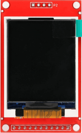
 Design with LCD TJC4832T135_011R in Cirkit Designer
Introduction
The LCD TJC4832T135_011R is a liquid crystal display (LCD) module manufactured by Taojingchi (TJC). It is designed for visual output in a variety of electronic applications, offering a high-resolution display and a user-friendly interface for seamless integration. This module is ideal for projects requiring graphical or textual output, such as industrial control systems, IoT devices, and consumer electronics.
Explore Projects Built with LCD TJC4832T135_011R
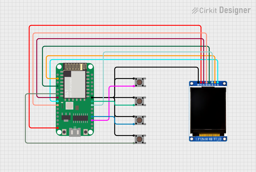 Open Project in Cirkit Designer
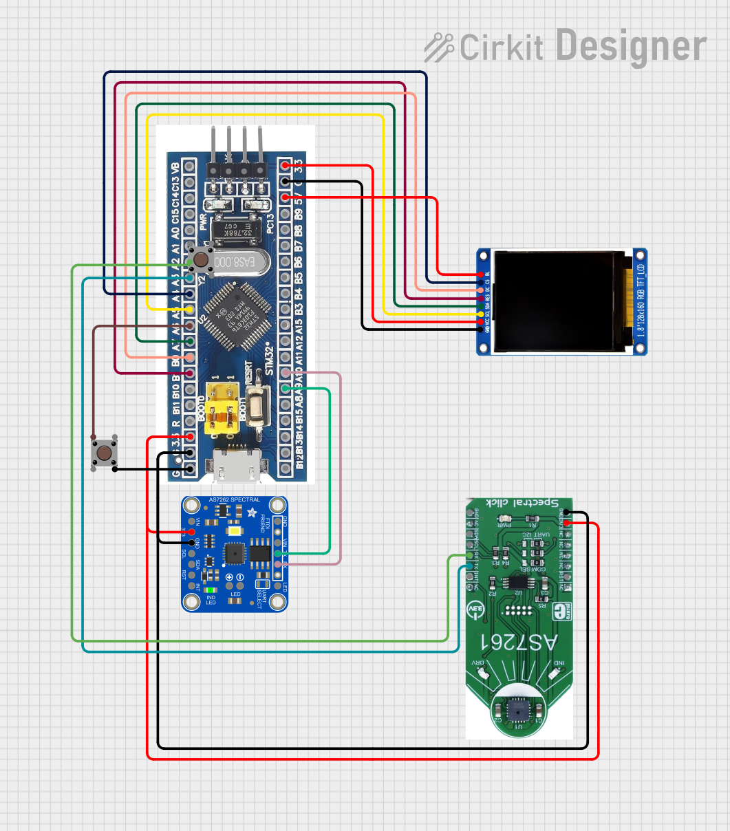 Open Project in Cirkit Designer
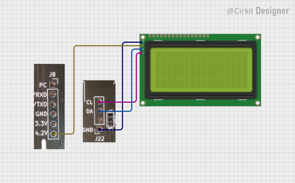 Open Project in Cirkit Designer
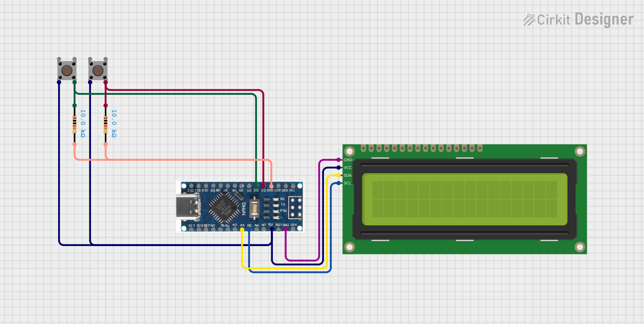 Open Project in Cirkit Designer
Explore Projects Built with LCD TJC4832T135_011R
Open Project in Cirkit DesignerOpen Project in Cirkit DesignerOpen Project in Cirkit DesignerOpen Project in Cirkit DesignerCommon Applications
- Industrial control panels
- Smart home devices
- IoT dashboards
- Consumer electronics with graphical interfaces
- Educational and prototyping projects
Technical Specifications
Key Technical Details
| Parameter | Specification |
|---|---|
| Manufacturer | Taojingchi (TJC) |
| Model Number | TJC4832T135_011R |
| Display Type | TFT LCD |
| Screen Size | 3.2 inches |
| Resolution | 480 x 320 pixels |
| Interface | UART (Serial Communication) |
| Operating Voltage | 5V DC |
| Operating Current | ~150mA |
| Backlight | LED |
| Touchscreen Support | Yes (Resistive Touch) |
| Operating Temperature | -20°C to 70°C |
| Storage Temperature | -30°C to 80°C |
Pin Configuration and Descriptions
The LCD module has a standard pin header for interfacing. Below is the pin configuration:
| Pin Number | Pin Name | Description |
|---|---|---|
| 1 | VCC | Power supply input (5V DC) |
| 2 | GND | Ground connection |
| 3 | TX | UART Transmit pin (data sent from LCD) |
| 4 | RX | UART Receive pin (data sent to LCD) |
| 5 | RESET | Reset pin (active low) |
| 6 | NC | Not connected (reserved for future use) |
Usage Instructions
How to Use the Component in a Circuit
- Power Supply: Connect the VCC pin to a 5V DC power source and the GND pin to the ground of your circuit.
- UART Communication: Use the TX and RX pins to establish serial communication with a microcontroller (e.g., Arduino UNO). Ensure the baud rate matches the LCD's default setting (typically 9600 bps).
- Reset: Optionally, connect the RESET pin to a GPIO pin on your microcontroller for manual or software-controlled resets.
- Touchscreen: If using the resistive touchscreen, ensure your software supports touch event handling.
Important Considerations and Best Practices
- Voltage Levels: Ensure the microcontroller's UART pins operate at 5V logic levels. If using a 3.3V microcontroller, use a level shifter.
- Baud Rate: Configure the UART baud rate in your microcontroller to match the LCD's default or configured baud rate.
- Initialization: Send the appropriate initialization commands to the LCD upon startup to configure the display mode and clear the screen.
- Avoid Noise: Use decoupling capacitors near the power pins to reduce electrical noise and ensure stable operation.
Example Code for Arduino UNO
Below is an example of how to interface the LCD TJC4832T135_011R with an Arduino UNO:
#include <SoftwareSerial.h>

// Define RX and TX pins for SoftwareSerial
SoftwareSerial lcdSerial(10, 11); // RX = Pin 10, TX = Pin 11

void setup() {
  lcdSerial.begin(9600); // Initialize UART communication at 9600 baud
  Serial.begin(9600);    // Initialize Serial Monitor for debugging

  // Send initialization command to the LCD
  lcdSerial.write(0xFF); // Start of command
  lcdSerial.write(0x01); // Clear screen command
  lcdSerial.write(0xFF); // End of command

  Serial.println("LCD Initialized");
}

void loop() {
  // Example: Send text to the LCD
  lcdSerial.write(0xFF); // Start of command
  lcdSerial.write(0x02); // Display text command
  lcdSerial.print("Hello, World!"); // Text to display
  lcdSerial.write(0xFF); // End of command

  delay(2000); // Wait for 2 seconds
}
Note: Replace the command bytes (0xFF, 0x01, 0x02) with the actual command set provided in the LCD's datasheet.
Troubleshooting and FAQs
Common Issues and Solutions
No Display Output:
- Verify the power supply voltage (5V DC) and ensure proper connections to the VCC and GND pins.
- Check the UART connection and ensure the baud rate matches the LCD's configuration.
Touchscreen Not Responding:
- Ensure the touchscreen is enabled in the LCD's settings.
- Verify that the touchscreen driver is correctly implemented in your software.
Corrupted or Garbled Text:
- Check for mismatched baud rates between the LCD and the microcontroller.
- Ensure the UART connection is stable and free from electrical noise.
LCD Not Initializing:
- Confirm that the initialization commands are sent correctly and in the proper sequence.
- Use the RESET pin to manually reset the LCD and retry initialization.
FAQs
Q1: Can I use this LCD with a 3.3V microcontroller?
A1: Yes, but you must use a level shifter to convert the 3.3V UART signals to 5V logic levels.
Q2: What is the default baud rate of the LCD?
A2: The default baud rate is typically 9600 bps. Refer to the datasheet for confirmation.
Q3: Does the LCD support custom fonts or graphics?
A3: Yes, the LCD supports custom fonts and graphics. Refer to the command set in the datasheet for details on uploading and displaying custom assets.
Q4: How do I update the firmware of the LCD?
A4: Firmware updates can be performed via the UART interface. Follow the manufacturer's instructions for the update process.
By following this documentation, you can effectively integrate the LCD TJC4832T135_011R into your projects and troubleshoot common issues.