How to Use ATtiny85: Examples, Pinouts, and Specs
Introduction
The ATtiny85 is a compact, high-performance microcontroller from Microchip Technology, designed for use in a variety of applications due to its small size and low power consumption. Based on the AVR RISC architecture, it features 8KB of in-system programmable flash memory, making it ideal for simple embedded projects, such as DIY electronics, wearables, and IoT devices.
Explore Projects Built with ATtiny85
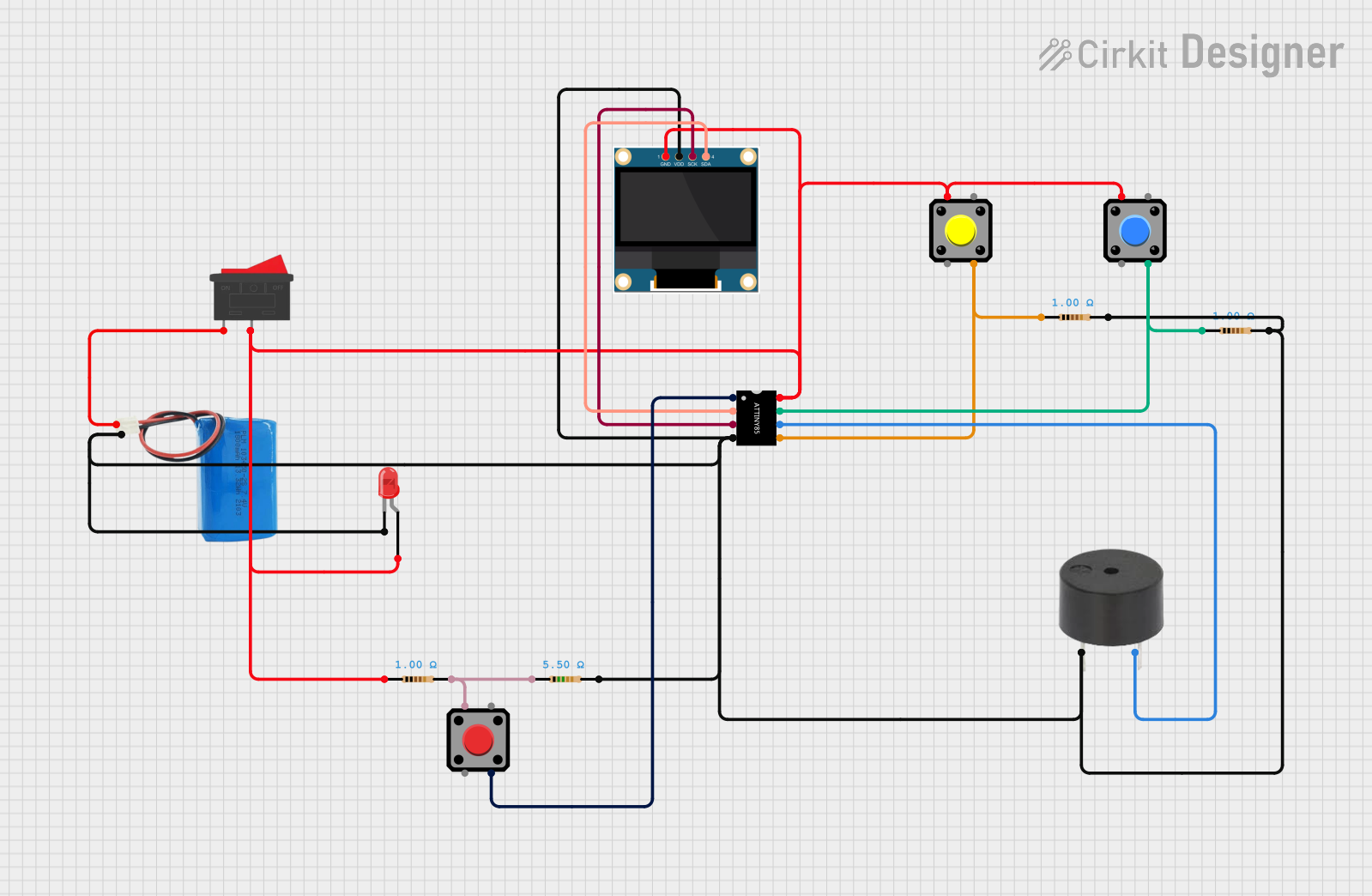
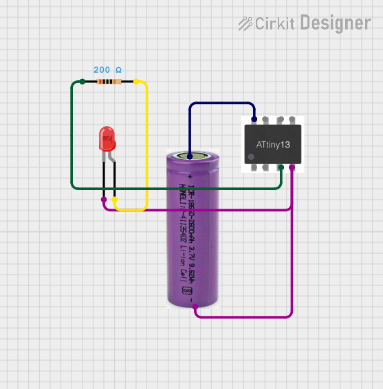


Explore Projects Built with ATtiny85
Common Applications and Use Cases
- Hobbyist electronics projects
- Wearable devices
- Simple IoT applications
- Prototyping and educational purposes
- Battery-operated devices
Technical Specifications
Key Technical Details
- Flash Memory: 8KB
- SRAM: 512 Bytes
- EEPROM: 512 Bytes
- I/O Pins: 6
- PWM Channels: 4
- ADC Channels: 4 (10-bit resolution)
- Clock Speed: Up to 20 MHz
- Operating Voltage: 2.7V - 5.5V
- Temperature Range: -40°C to +85°C
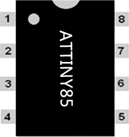
Pin Configuration and Descriptions
| Pin Number | Name | Description |
|---|---|---|
| 1 | PB5 | Reset and programming interface, also serves as I/O pin |
| 2 | PB3 | Analog input or digital I/O, ADC3 |
| 3 | PB4 | Analog input or digital I/O, ADC2 |
| 4 | GND | Ground pin |
| 5 | PB0 | Digital I/O, OC0A (PWM output) |
| 6 | PB1 | Digital I/O, OC0B (PWM output), ADC1 |
| 7 | PB2 | Digital I/O, INT0 (external interrupt), ADC0 |
| 8 | VCC | Positive supply voltage |
Usage Instructions
How to Use the ATtiny85 in a Circuit
Powering the ATtiny85:
- Connect the VCC pin to a power supply within the operating voltage range (2.7V - 5.5V).
- Connect the GND pin to the ground of the power supply.
Programming the ATtiny85:
- Use an AVR programmer or an Arduino as an ISP (In-System Programmer) to upload code to the ATtiny85.
- Ensure the correct pin mapping is used when programming the ATtiny85 with an Arduino.
Connecting I/O Pins:
- Configure the I/O pins as input or output according to your application needs.
- Use the PWM pins for analog output applications like dimming LEDs or controlling motor speed.
Using ADC Channels:
- Connect analog sensors to ADC pins for analog-to-digital conversion.
- Ensure proper reference voltage is set in your code for accurate readings.
Important Considerations and Best Practices
- Always check the pinout and datasheet before connecting the ATtiny85 to other components.
- Avoid supplying voltage higher than the maximum rating to prevent damage.
- Use decoupling capacitors close to the VCC and GND pins to stabilize the power supply.
- Consider using an external clock source for applications requiring precise timing.
Troubleshooting and FAQs
Common Issues
ATtiny85 not responding to programming:
- Check connections to the programmer.
- Ensure that the correct device is selected in the programming software.
- Verify that the ATtiny85 has not been set to use an external clock source without one being present.
Incorrect behavior in I/O operations:
- Double-check the pin configuration in your code.
- Ensure that the power supply is stable and within the specified range.
Solutions and Tips for Troubleshooting
- If the ATtiny85 is unresponsive, try using a high-voltage programming mode if available.
- For analog readings, calibrate the ADC regularly to maintain accuracy.
- Use a multimeter to verify voltage levels and continuity in your circuit.
FAQs
Can the ATtiny85 be used with Arduino IDE?
- Yes, with the addition of the appropriate board package, the ATtiny85 can be programmed using the Arduino IDE.
What is the maximum current per I/O pin?
- The maximum DC current per I/O pin is 40 mA.
How can I reduce power consumption for battery-operated devices?
- Utilize sleep modes and disable unused peripherals to conserve power.
Example Code for Arduino UNO as ISP
#include <avr/sleep.h>
#include <avr/power.h>

void setup() {
  // Set up code here
}

void loop() {
  // Main code here

  // Example: Entering sleep mode to save power
  set_sleep_mode(SLEEP_MODE_PWR_DOWN);
  sleep_enable();
  power_all_disable(); // Disable all peripherals
  sleep_mode();        // Enter sleep mode

  // The device will wake up here after an interrupt
  power_all_enable();  // Re-enable all peripherals
  sleep_disable();
}
Note: This example demonstrates how to put the ATtiny85 into a power-down sleep mode to conserve energy, which is useful for battery-operated devices. The actual implementation will vary based on the specific application and the required wake-up sources.